- Joined
- 4 May 2012
- Messages
- 9
- Reaction score
- 0
- Country

Howdy Pardners,
I've got a Wylex consumer unit with 'flexible bus bars'. Each piece of bar has one cranked pin at the end that's supposed to slot into the RCDs/Main Switch. But because it's cranked - offset a little compared to the other pins - when you tighten down on it the MCBs are pushed away from the DIN rail out of alignment with the RCDs. AFAICS it makes no sense for the end pin to be 'cranked' like this since the RCD live output lines up perfectly with the MCB live inputs. Any idea what's going on here? I can get away with cutting off this cranked pin because I dont need 5 circuits on either of the RCDs, but how come it's like this in the first place?
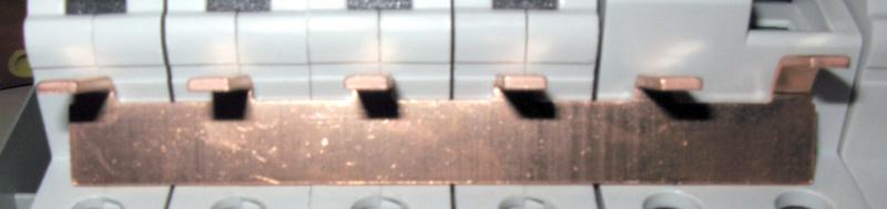
Here's what the bar kinda looks like with the pins facing you - 5 pins and one 'cranked' 'supply' pin at the end:
- - - - - _
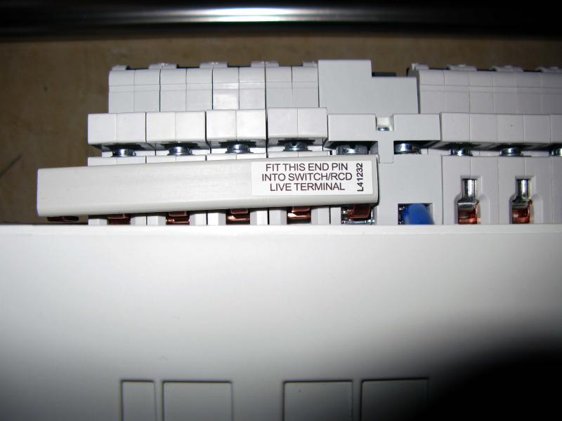
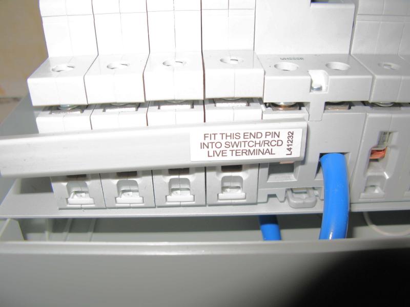
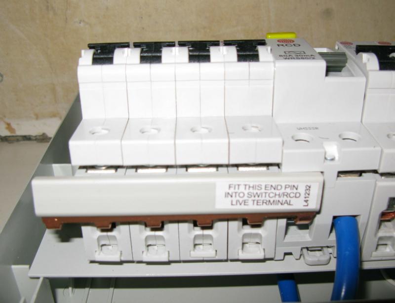
UPDATE: here's some photos.
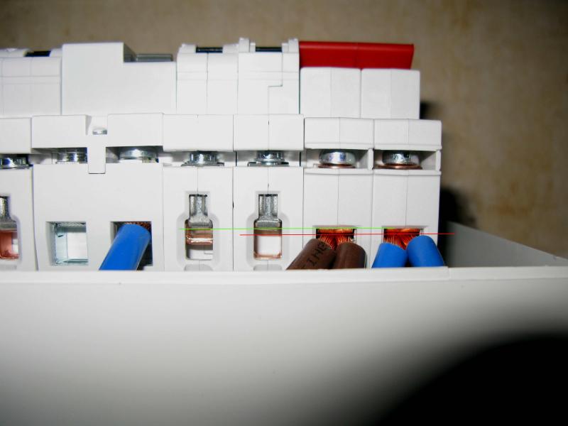
Terminals line up:
Looks like main switch might be offset.
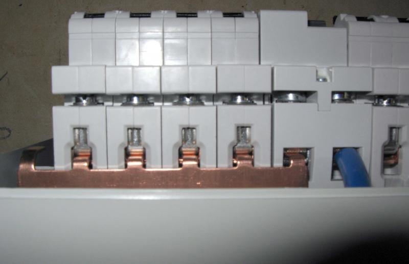
With bar fitted, MCBs are pulled out of line.
Unclipped, the MCBs are way off.
Cheers. [/img]
I've got a Wylex consumer unit with 'flexible bus bars'. Each piece of bar has one cranked pin at the end that's supposed to slot into the RCDs/Main Switch. But because it's cranked - offset a little compared to the other pins - when you tighten down on it the MCBs are pushed away from the DIN rail out of alignment with the RCDs. AFAICS it makes no sense for the end pin to be 'cranked' like this since the RCD live output lines up perfectly with the MCB live inputs. Any idea what's going on here? I can get away with cutting off this cranked pin because I dont need 5 circuits on either of the RCDs, but how come it's like this in the first place?
Here's what the bar kinda looks like with the pins facing you - 5 pins and one 'cranked' 'supply' pin at the end:
- - - - - _
UPDATE: here's some photos.
Terminals line up:
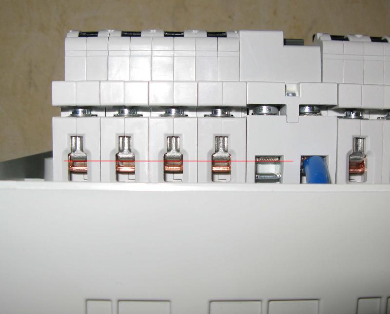
Looks like main switch might be offset.
With bar fitted, MCBs are pulled out of line.
Unclipped, the MCBs are way off.
Cheers. [/img]

 I just googled slidey bit so no worries. Yes, the bar is clamped properly in each terminal with the sliding part of the terminal beneath pulled up against the pins.