Bypass valve location

Joined
28 Aug 2011
Messages
10
Reaction score
0
Location
Wiltshire
Country
United Kingdom
Hello. I have fitted smart TRVs to nearly all my rads. However, when only 1 or 2 rads calling for heat then system noise is quite loud. I've been advised bypass valve will sort out noise and avoid me having to leave one rad without a TRV. The easiest place for me to access is directly above boiler, but I think this is too close. Next easiest place is the eaves of our loft conversion. The flow and return are probably about 3m pipe length from boiler. Could I put the bypass here or is this too far away?

Combi boiler, no HW tank.
 
Sponsored Links
What boiler do you have? Somewhere in the installation instructions it'll probably specify bypass requirement & distance. Just above the boiler would be poor, 3m might be enough.
 
Worcester 37Cdi. Manual only says
"An automatic bypass may be required,
(downstream of the pump), in order to
maintain the minimum flow-rate through the
appliance."
 
The further from the boiler the bypass is the better it'll work (within reason of course)- if you can get to 5 or 6 metres that seems to be a common figure quoted for boilers that require bypasses (rather than suggest them). Too near the boiler & the flow losses naturally in the system may mean it operates continually, reducing your system efficiency.
 
Sponsored Links
@oldbutnotdead many thanks. I emailed Worcester and they've just come back and said 1-2 meters. I've asked if 3 will be ok.
Does it matter where on system the bypass is fitted? Like I said loft seems the easiest place to access. Could probably get to 4 meters also.
 
Loft is fine (long as you lag it so it doesn't freeze up). Ideally wants to be on the main 22mm flow & return from the boiler, obviously before any motorised valves (doesn't sound as if you have any so not a problem). Usual setting for them is 0.2 bar
 
I think when the loft rads were put in they tee'd off the main flow and return just above the boiler. So the tee one way goes to the first floor rads and the other tee goes to the loft. I think the flow to the loft is all 15mm plastic. Problem on the 15mm?
 
Would it matter that the bypass goes on 15mm pipework on a section of the heating system that is essentially an extension?
 
Putting it on the 15mm will be fine, you may need to experiment with the bypass pressure setting but as long as there are no motorised valves in way it'll be in the ballpark at 0.2 bar & work much better than putting it just above the boiler
 
I have a similar question about the bypass valve location.
My system comprises a new Vaillant heat-only boiler, pressure vessel, DHW cylinder, 3 Motorised Valves (1 x cylinder, 2 x CH zones) and 15 rads with 12 TRVs. Vaillant specify an Auto Bypass Valve (ABV) is fitted no less than 1.5m from the boiler.

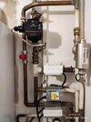
The original system already had a bypass pipe which Tee's off from the Flow after the 3 MVs, at a distance of 1.3m of pipe length away from the boiler (see the attached picture). This pipe had a fixed valve (seen in the picture just behind the pump) set to slightly open, to which an ABV has recently been added, located 1.6m of pipe length away from the boiler. The bypass pipe Tee's into the Return 1.0m of pipe length from the boiler, so the total length of the current bypass circuit, taken from the boiler connections, is 3.1m.

The bypass does not work correctly in that it always allows hot water through (with all the TRVs set to fully open). Setting the ABV to max (=0.6) does not help.
My questions:
1) Does Vaillant's minimum 1.5m specification relate to where the bypass pipework Tee's off from the Flow (1.3m) or where the ABV is located (1.6m)?
2) Is the bypass malfunction due to a distance issue (1.3m, 1.6m or 3.1m) and/or the fact that the pipework Tee's off after the MVs rather than between the pump and the MVs? (This design has been there 30 years, so perhaps the bypass never worked well and I just did not realise it).
3) Would it be helpful to make the bypass pipework longer by installing a back & forth zig-zag configuration of bypass pipes on an adjacent wall and placing the ABV within that zig-zag, perhaps 2.5m from the boiler?
Thank you
 

Attachments

  • IMG_20230522_123657.jpg
    IMG_20230522_123657.jpg
    242.1 KB · Views: 129
What mode/setting is the pump??. The ups3 defaults to fixed (CC3) speed mode which at 6.4M head which is invariably too high for most systems as it will pump in constant pressure mode for most home installations, I can't recall the PP settings just now but PP3 might well satisfy your needs or nearly certainly one of the CP ,(constant pressure) modes corresponding to a head of 3M (CP1??)
 
Last edited:
Hi, regarding the pump mode, this has varied as follows.
Background: My house is on 4 floors - the boiler/pump/MVs/DHW cylinder are in the basement, while the top floor rads are about 9m above.
The UPS3 pump has Constant Speed 1-3, Proportional Pressure 1-2 and Constant Pressure 1-2.
There have been several phases to my heating system upgrade over the past few months, using different pump modes:
(1) New Vaillant EcoFit Pure heat-only boiler. Bypass pipework was retained from old non-condensing system, with a fixed valve slightly open. To achieve some modulation I used pump mode PP2 which seemed to work OK, although I was not paying attention to the bypass at that time and don't know how it was performing.
(2) Added Vaillant controls (SensoComfort 720, VR71 wiring centre, VRC693 weather sensing, boiler D00 heat output set to Auto). I was advised that PP mode may not be compatible with weather sensing modulation (they would 'fight' each other), so switched to CP2 which seemed to work OK.
3) Added an Auto Bypass Valve and noticed the bypass pipework was always hot (which might have been the case all the time). I was advised an ABV might not work well with the pump in CP mode as the ABV works by detecting pressure changes, so switched to CS2, but the bypass is still always hot.
 
Will reply in more detail later, presently AWOL but will be home on Thursday, if you only require a bypass when the boiler shuts down then you could install a normally open motorized valve wired to the wiring center terminal where the orange wires from all the motorized valves are connected, if any motorized valve is opened then the bypass will close and will only open when all the motorized valves are closed.
 
I don't know whether the bypass is only required when the boiler shuts down. Vaillant's installation manual specifies an ABV and does not mention a motorised valve to control the bypass. Also an ABV implies (to me) that the bypass is meant to respond variably as the TRVs close, although I believe the boiler does modulate according to the load, but the pump does not.
 
The UPS3 3 has effectively 5 constant pressure modes and 2 proportional PP modes, PP1 is generally far too low at 1 to 2m, PP2 should be OK at 1.6 to 3.7m as it will pump 1m3/hr (16.66LPM) at 2.5M, the problem with ABV that if you set it up to just pass the minimum required at 1.6bar it will then pass 25/30% more when running at 2.5M or so, it is recommended to put a tachosetter in series with the ABV and run in CP mode, say CP1 at 3M with the UPS3. search "Grundfos Alpha 2 15-60 130 Setting" thread and you will get the gist of this set up
 

Attachments

  • ups3-datasheet (1).pdf
    543.9 KB · Views: 67

DIYnot Local

Staff member

If you need to find a tradesperson to get your job done, please try our local search below, or if you are doing it yourself you can find suppliers local to you.

Select the supplier or trade you require, enter your location to begin your search.


Are you a trade or supplier? You can create your listing free at DIYnot Local

 
Sponsored Links
Back
Top