Changing an old Room Thermostat

Joined
4 Apr 2018
Messages
5
Reaction score
0
Country
United Kingdom
fDKK4x
Hello,

I'm currently looking to change my central heating thermostat. At present i have a Honeywell T40 and was looking to replace it with a thermostat with a digital temperature readout. I have been looking around and a Heatmiser DS1-L looks to fit what i'm looking for. I also have a Siemens RWB29 2 channel programmer for the boiler so i don't think a programmable thermostat is necessary.

The T40 seams to be very inaccurate at maintaining heat in the living room where it is. Sometimes it feels like its got a 5 degree switching differential and can be slow to respond to heat changes in the room.

Fist of all, would the RWB29 be a suitable replacement for the T40?

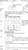
Secondly, if it is suitable, i have been looking at the manual for the RWV29 and comparing the wireing to what i currently have in the T40, pictured bellow

IMG_5598.jpg


The manual for the RWB29 who2w 2 options, Volt free and 23v switching mode.
IMG_5601.jpg


Would i be using the 230v Switching mode?
Am i interpreting it correctly that i would need to add a small jumper cable to bridge between A1 and L?
Is anyone able to give me a simple guide on how to switch the wires from the T40 into the RWB29 please?

Thank you all in advance for your time,
Paul
 
Sponsored Links
The wiring will be as per the right hand diagram for 230V.

You can identify what each of the Honeywell wires does from the diagram in the lid.

The wire in Honeywell terminal (1) = Live from programmer = DS1-L (A1) Terminal
The wire in Honeywell terminal (2) = Neutral = DS1-L (N) Terminal
The wire in Honeywell terminal (3) = Switched live = DS1-L (A2) Terminal

Then add a Link between DS1-L Terminals (L) and (A1)

Please note. With the 3 wires that are currently present, the live supply to the thermostat will however disappear when the RWB29 programmer switches the heating 'off'. How the DS1-L will react to that I don't know. Most non-programmable digital thermostats designed to be controlled via a separate programmer have batteries in to keep the display on and maintain the setting when the programmer switches off. An additional permanent live wire would overcome this but additional wiring would need adding.

Fist of all, would the RWB29 be a suitable replacement for the T40?
I'm not sure what you mean by this? The RWB29 is a programmer and controls the 'time' of operation. The T40 is a thermostat and controls the 'room temperature' they are different devices, with different functions, one can't replace the other.

EDIT
For the record the Thermostat is actually a T6360B but I've used T40 as that is what you have called it.
 
Last edited:
Hi Stem,
That’s great, thanks for getting back to me.

Apologies for the confusion, I meant to ask if the DS1-L was a suitable replacement for the T40.

Are you able to recommend a digital thermostat that would get around the issue of having the power cut out to it when the CH goes off on the programmer?

Alternatively, would it be okay to take a single core from a nearby plug sucket live to the live on the DS1-L as a permenant live for the theremostat or would this not meet regulations?

Thanks
Paul
 
The non RF versions of the following would be OK.

Honeywell DT90E
Danfoss TP 5000 Si
Drayton Digistat

All are battery powered, and so don't need the neutral connection either. You would just use the live wires presently in the Honeywell terminals (1) and (3)

would it be okay to take a single core from a nearby plug sucket live to the live on the DS1-L as a permenant live for the theremostat or would this not meet regulations?
It would work if you connected it to (L), but you would need to insert a 3A fuse in it somewhere, and you wouldn't then need the link between (L) and (A1) However, as you suspect, it is not good wiring practice. Ideally the entire heating system should be supplied via the same fused connection unit, so that when it's switched off, everything associated with it is isolated.
 
Sponsored Links
So the drayton digistat 30002 looks the best fit for us.

I’ve attached a screen shot of the wiring diagram.

Would I be right In Thinking that
Honeywell term 1 -> Digistat ‘COM’
Honeywell term 2 -> Digistat ‘N’
Honeywell term 3 -> Digistat ‘ON’

Or have i got it all completely the wrong way round :ROFLMAO:

I had a feeling crossing circuits over wouldn’t be a good idea!

Thank you so much for your help!
 

Attachments

  • 94A3032B-19B7-4508-AAD5-4B4D3820765D.png
    94A3032B-19B7-4508-AAD5-4B4D3820765D.png
    416.3 KB · Views: 621
The T40 seams to be very inaccurate at maintaining heat in the living room where it is. Sometimes it feels like its got a 5 degree switching differential and can be slow to respond to heat changes in the room.
This is normally caused by a missing neutral; but as it appears to be connected to terminal 2, we can discount that. The other cause could be that the wires to terminals 1 and 3 have been reversed. 1 should connect to the programmer and is the Switched Live to motorized valve or boiler.

If you have a multimeter (and know how to use it ;)) measure the voltage between 1 and N, when timer is ON, while turning stat up and down. It should show 240 Vac all the time. checking between 3 and N should give 0 Vac when turned right down and 240Vac when turned right up. If you get the opposite effect (240 V all the time on 3, 240 V or 0 V on terminal 1) the wires to terminals 1 and 3 need to be swapped over.

Hi D_hailsham,
Already done this! I get a constant 230v on 1 when the CH is on and 230v comes on and off on 3 when turning the dial.

I think the thermostat itself is broken.

Thanks
Paul
 
Hi D_hailsham,
Already done this! I get a constant 230v on 1 when the CH is on and 230v comes on and off on 3 when turning the dial.

I think the thermostat itself is broken.

Thanks
Paul
I think you're right about it being broken. A friend of mine had same roomstat with similar problem. There was a wire connected to terminal 2 (for the anticipator heater), but it wasn't connected to neutral at the other end. Thought that was causing the high differential. Corrected it but it made no difference. At first I'd assumed the stat had a bimetallic diaphragm sensing element (unlikely to fail) but investigating on the internet it turns out it's a filled bellows, which must have leaked. It might be worth just checking the anticipator has a neutral, but if the stat worked OK in the past but now doesn't it sounds like it's had it.
 
So the drayton digistat 30002 looks the best fit for us.

I’ve attached a screen shot of the wiring diagram.

Would I be right In Thinking that
Honeywell term 1 -> Digistat ‘COM’
Honeywell term 2 -> Digistat ‘N’
Honeywell term 3 -> Digistat ‘ON’

Or have i got it all completely the wrong way round :ROFLMAO:

I had a feeling crossing circuits over wouldn’t be a good idea!

Thank you so much for your help!

Sounds good to me. You don't need the neutral, but they kindly provide a terminal for you to use. Odd then that they show an accelerator heater connected to it, that will be permanently 'on' rather than only 'on' when calling for heat...using a wire that is 'not required' :confused:

Capture.JPG
 
Sounds good to me. You don't need the neutral, but they kindly provide a terminal for you to use. Odd then that they show an accelerator heater connected to it, that will be permanently 'on' rather than only 'on' when calling for heat...using a wire that is 'not required' :confused:

View attachment 139638

Agreed the connections shown look odd. You wouldn't think a published diagram would get it wrong, but I'd expect it to be wired as per the diagram in the original post - anticipator energised when calling for heat. Maybe it is but diagram wrong. Easy enough to check if you have the stat on the bench.
 
Sounds good to me. You don't need the neutral, but they kindly provide a terminal for you to use. Odd then that they show an accelerator heater connected to it, that will be permanently 'on' rather than only 'on' when calling for heat...using a wire that is 'not required' :confused:

View attachment 139638

Thanks!

Would it be beneficial to just make the neutral safe and leave it behind the thermostat in the wall if it is not required?

Just for my own education....
The switched live from the programmer would constantly supply power to the thermostat when the CH is on
The Call for heat only has power when the thermostat falls bellow the temperature set?
 
I've got the same Thermostat and was thinking of changing to digital as well.

We have a standalone programmer so just need the stat. Are there any that use 240v with a battery backup as well or do they all run off battery only?.
 
Would it be beneficial to just make the neutral safe and leave it behind the thermostat in the wall if it is not required?
You could. That is probably what I would do.

Just for my own education....
The switched live from the programmer would constantly supply power to the thermostat when the CH is on
Correct.

The Call for heat only has power when the thermostat falls bellow the temperature set?
Also correct.
 
I've got the same Thermostat and was thinking of changing to digital as well.

We have a standalone programmer so just need the stat. Are there any that use 240v with a battery backup as well or do they all run off battery only?.

Most digital thermostats (that provide temperature control only) have batteries, because they are designed to operate in conjunction with a programmer that only provides power when the programmer is set to have the heating 'on' so the batteries are there to maintain the display and selected setting.

Programmable thermostats that include time control and so are not used in conjunction with a separate programmer can be (but are not always) mains powered, because the mains supply will not be interrupted.

The thermostats I mentioned earlier are battery powered and would be suitable for use with an existing programmer:
The non RF versions of the following would be OK.

Honeywell DT90E
Danfoss TP 5000 Si
Drayton Digistat

All are battery powered.

I'm not aware of any that are 230V powered with a rechargeable battery 'back up' but I would imagine that if they do exist that they would only be designed for power failure only and not regular use under rechargeable battery power. There wouldn't really be a need for such a unit. I have a Danfoss thermostat with replaceable batteries and they last about 3 years.
 
Last edited:
Thanks for the in depth reply stem, much appreciated!.
 

DIYnot Local

Staff member

If you need to find a tradesperson to get your job done, please try our local search below, or if you are doing it yourself you can find suppliers local to you.

Select the supplier or trade you require, enter your location to begin your search.


Are you a trade or supplier? You can create your listing free at DIYnot Local

 
Sponsored Links
Back
Top