Drainage advice for extension

Joined
11 Feb 2021
Messages
47
Reaction score
1
Country
United Kingdom
Hi..I'm really hoping someone can advise. We're looking at building an extension which will be over an existing Inspection Chamber. We are at the start of the terrace so the only drains the feed into the chamber is the main foul water from the house WC and the other being the kitchen. There is a rodding eye which is located in the property (I suppose that's how they built them in the 80s). So there is rodding downstream for the WC flow and the kitchen can be rodded from an outside gully or the sink also downstream. The main drain flow can be rodded from the inspection chamber. All drains will be linted over where needed.

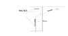
With the extension, Thames Water have said we can do what is required as its a private drain with nothing flowing into it. The plan we have so far is to breakout the current inspection chamber and directly connect the kitchen and existing wc foul water to the main drain. There will still be rodding access downstream as noted above. We will also be installing a new MH with a new WC connection which will connect to the main drain so the main drain can also be rodded downstream. There is next doors MH to rod upstream if need be. Here are some sketches..I've never been a Leonardo so be kind ;)..any advise will be much appreciated as we although we think we have all possible blockages covered we're hoping this is the right way of going about it...thanks
 

Attachments

  • PostDr.jpg
    PostDr.jpg
    33.1 KB · Views: 180
  • PreDr.jpg
    PreDr.jpg
    24.2 KB · Views: 145
Sponsored Links
I’d be concerned that there are a few bends under the extension, and the leg from the kitchen might not be roddable, can’t you run all the new connections to the new IC, then just a single leg out of the new IC back under the building with the bend as close as poss to the IC?
Basically run “sewage” and “kitchen” lines separately to the new IC.
 
As above, I'd take all the laterals outside the footprint of the new extension to the new chamber, then run the outlet from that back under the building, and rejoin with as slow a bend as possible. Gives opportunity then for all laterals to be rodded from outside, and the main run can be accessed upstream. (You really do not want to be trying to jet a blocked run from upstream, inside the building!)

Where does the main run go to off the bottom of the drawing?
 
Thanks for the replies. The main run goes off to next door and finally to the main sewer on the street.
The kitchen lateral isn’t an issue. The issue we have with running the laterals to the new IC is that the existing WC foul gradient is quite low. The new IC will be about 3 meters away from the wc pipe start at the building end. We can’t raise this as the rest of the flow pipe is under the existing building. To get a 1:40 fall to the new IC and then a further 1:40 back to the main run is the problem. The return run will come back under the main drain flow. Ideally I would like to run everything out and then a single return back in but just can’t get the slopes to work
 
Sponsored Links
Any scope for rerouting the stack out to the to rear (top of drawing), turn it 90° then run across to the left, before turning 90° again and picking up the line of the new run? The fact it's already on a shallow fall would concern me, and then not having any external access to that shallow run, concerns me even more. (Having a discussion about that on martysmarty's post!)

The other issue is, whilst Thames will have no concerns, (as it's not their sewer), the work will still by Notifiable under Building Regs and I'd be very surprised if the BCO would allow a blind lateral under the building from a stack, without adequate provision for clearing it should need ever arise. They may allow an internal rodding access, but it'll take a brave person to open it, let alone jet from it.
 
Rerouting to the top isn't possible as its a public path. I agree running the laterals out is the best option and is the one I want to go for but the fall is a big issue. The slopes we are looking at are WC drain from building to new IC 4.5 meters @ 1:40 so 113 mm + 100 mm for the IC connector fall (I think these are spaced at 100 mm below each other) + 2.2 meters back to the main run (might even be more if we come back at a different angle) which is a further 5 mm slope. So total slopes are 268 mm. Am I getting this wrong?

Also could I potentially use a level invert chamber rather than the regular stepped chamber?

"Level invert chambers are often used when the installer has little fall to play with on the pipe run" seems like this might be an option. Question is would I be able to maintain a a 1:40 slope if I used it? Thanks
 
Last edited by a moderator:
Alternatively could I put in a rodding eye for the kitchen connection and another for the sewage join to the main run so I could rod these upstream which in theory would accomplish running the lateral out to the new IC
 
It's obviously up to the building inspector, but that's literally a crap layout with the main soil stack and the kitchen sink on a blind connection run, a tight bend and with no access - plus that may well suck the sink trap out every time you flush the toilet
 
you're right. The more I think about it and from the comments I'm going to have to figure out a way to run the laterals out and then back in again. The return is already coming back in with the new toilet so really its just the kitchen and existing WC to run. Any thoughts on a level invert chamber as this might allow us to maintain the slope
 
The house/extension is on the boundary bottom is the neighbour top is a public path. I have no scope of running the flow to the top or bottom as it won't be on our property. The 'only' issue I have is the fact the return will come below the the main run if we are to maintain the slopes and I can't raise the existing WC exit as its under the building
 
My calculation's on the distance/fall give the same result, if a Level Invert chamber is used, then you need a minimum of 168mm height differential to gain a 1:40 fall over the stated distance. Is that achievable?

The 1:40 can be reduced under some circumstances, but that in itself can lead to issues, especially with the 6 litre flushes modern toilets are using.
 
Leave the existing drainage layout extend it to a new sealed chamber and stub stack in the WC. Renew any clay pipe under the extension with plastic.
 
I'm leaning towards taking the laterals out and back in again. I have re-measured (in the light of day) and the exact runs are from the house to the new IC 4 meters and 2.4 meters back from the new IC to the main run. So total runs are 160 mm. We have a slope of 150 mm available. So if I use a level invert chamber, I need to 'find' 10 mm to make it work at a 1:40 ratio
 
Also these level invert chambers seem to come in sizes of 250 mm, would this suffice or would I need to build it out to 320 mm or even 450 mm? The depth of the new IC will be a max of 600 mm so I'm hoping the 250 mm would be ok
 

DIYnot Local

Staff member

If you need to find a tradesperson to get your job done, please try our local search below, or if you are doing it yourself you can find suppliers local to you.

Select the supplier or trade you require, enter your location to begin your search.


Are you a trade or supplier? You can create your listing free at DIYnot Local

 
Sponsored Links
Back
Top