
- Joined
- 4 Jan 2020
- Messages
- 2
- Reaction score
- 0
- Country

I am trying to replace a British Gas UT2 (which google tells me is a rebadged Drayton LP711 single channel controller) with a Nest 3rd Generation Heatlink (HL) and stat.
I've used the excellent resources on this forum to get me so far, but have hit the limits of my abilities and would appreciate some advice. A mans got to know his limitations....
Picture of the controller wiring before any works:
The existing British Gas RS1 stat, along with wiring to the boiler are both terminated here.
I have wiring to N L 1 3 4.
Firstly I have disconnected the wiring for the old stat from the controller.
This leaves:
N & L - I have single wires into each, coming from a separate fused 240v feed to the controller.
3 - Hot Water (HW) ON
4 - Central heating (CH) ON
The wire that was in 1 came from the disconnected stat.
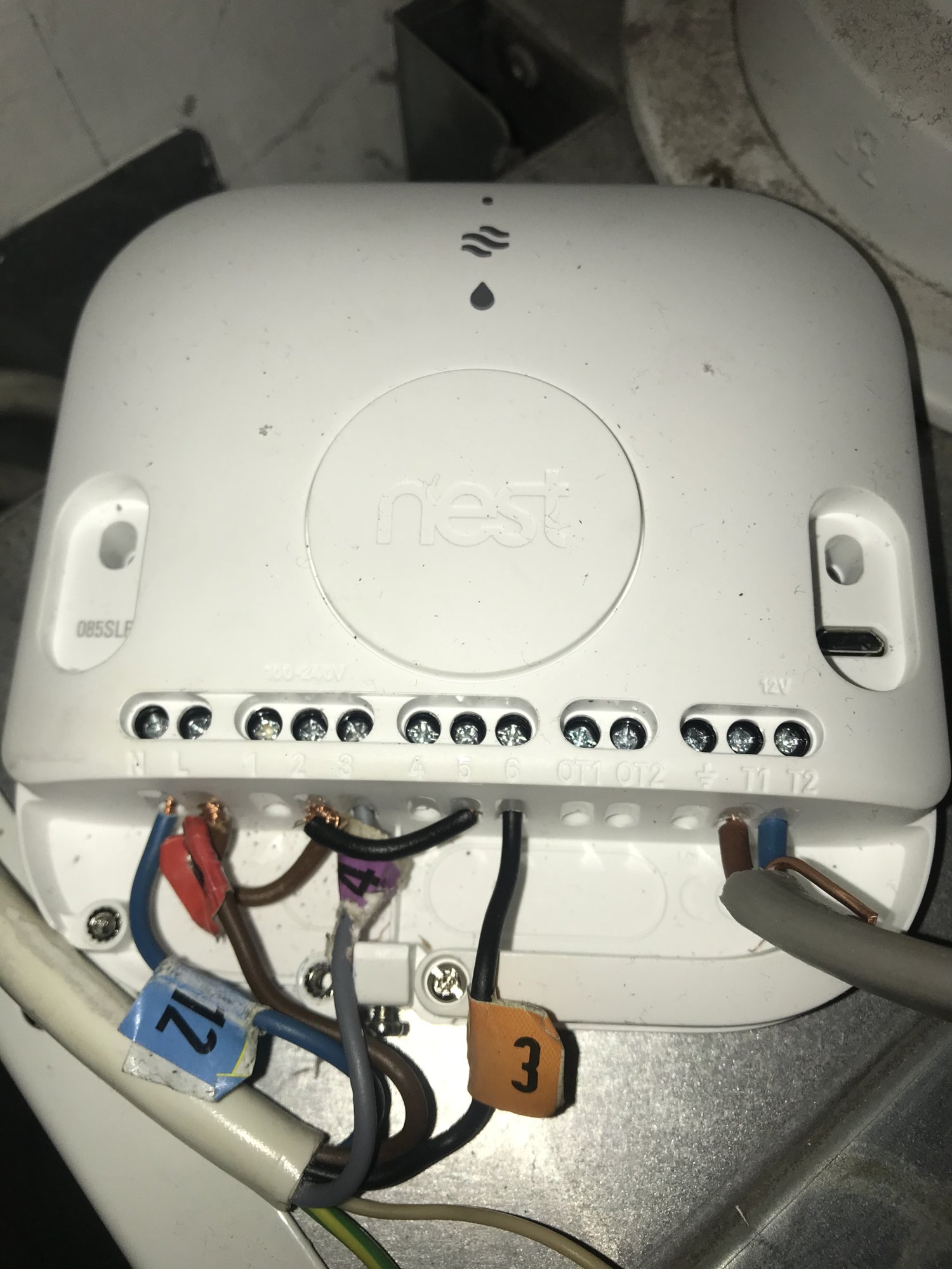
So, I have disconnected the N & L from the old controller wiring and used these to power the Nest HL.
Wire 3 (HW) has been connected to HL 6 (Call for Water)
Wire 4 (CH) has been connected to HL 3 (Call for Heat)
I have connected the Nest stat to T1 and T2 on the HL and this is powered and configured.
So far so good.
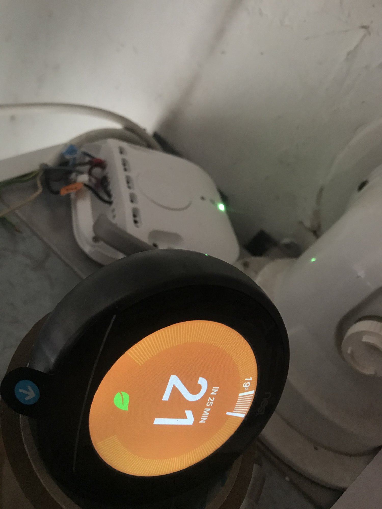
Now if I test at this point in the install I have hot water working but no heating. I'm triggering the heating by turning up the stat (there's an audible click) but I've tried also pressed the button on the front of the HL. I wasn't actually expecting anything to be working at this point, as I haven't jumpered the live feed on the heatlink to ports 2 and 5.
When I connect the L on the HL to 2 and 5 I get no change in behaviour. Here's what it looks like.
Troubleshooting.
If I disconnect the HL 6 Call for Water, leaving HL 3 Call for Heat there's no change.
Now for no real purpose, if I now disconnect HL 3 Call for Heat and replace it with the wire that was in HL 6 (Call for Water) I get both heating and hot water, I think together. The boiler is successfully triggered by the stat for heating.
My understanding of the ports on the HL ports 1-3 (HW) is that the live feed presented to port 2 will be connected to port 3 when ON and connected to port 1 when OFF. Ditto for ports 4-6 (CH). I have also observed that if I twist together wires in 2 (L) and 3 (Call for Heat) this doesn't however trigger the boiler CH.
I've had a look at the wiring terminated in the boiler and observed that the black wires terminate on LR and the grey wires on LSW. I can post pics of this end if useful.
That's all I've got. Along with a bit of a cold house and that particular type of understanding look on my wife's face")
All help and advice appreciated.
I've used the excellent resources on this forum to get me so far, but have hit the limits of my abilities and would appreciate some advice. A mans got to know his limitations....
Picture of the controller wiring before any works:
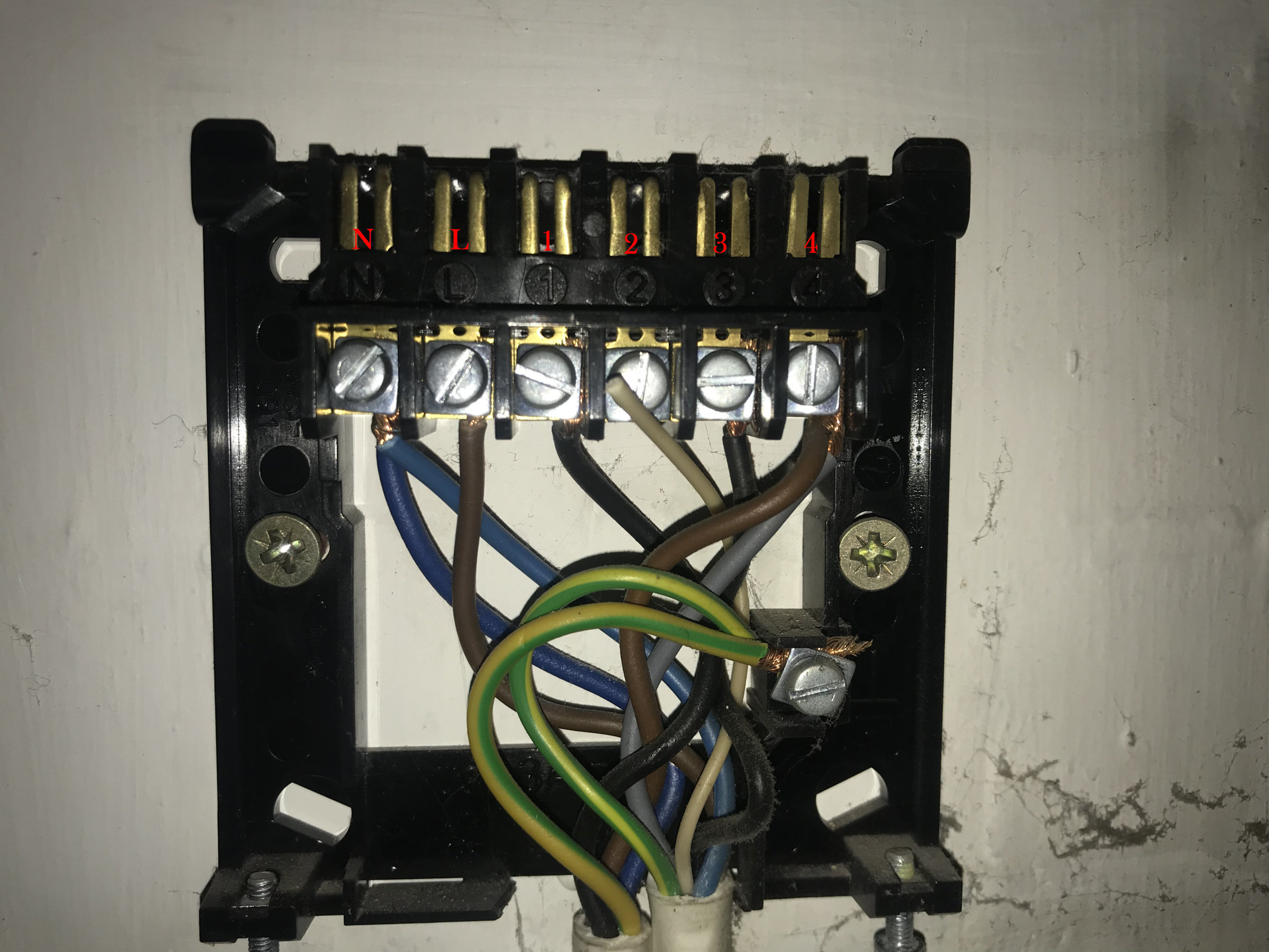
The existing British Gas RS1 stat, along with wiring to the boiler are both terminated here.
I have wiring to N L 1 3 4.
Firstly I have disconnected the wiring for the old stat from the controller.
This leaves:
N & L - I have single wires into each, coming from a separate fused 240v feed to the controller.
3 - Hot Water (HW) ON
4 - Central heating (CH) ON
The wire that was in 1 came from the disconnected stat.
So, I have disconnected the N & L from the old controller wiring and used these to power the Nest HL.
Wire 3 (HW) has been connected to HL 6 (Call for Water)
Wire 4 (CH) has been connected to HL 3 (Call for Heat)
I have connected the Nest stat to T1 and T2 on the HL and this is powered and configured.
So far so good.
Now if I test at this point in the install I have hot water working but no heating. I'm triggering the heating by turning up the stat (there's an audible click) but I've tried also pressed the button on the front of the HL. I wasn't actually expecting anything to be working at this point, as I haven't jumpered the live feed on the heatlink to ports 2 and 5.
When I connect the L on the HL to 2 and 5 I get no change in behaviour. Here's what it looks like.
Troubleshooting.
If I disconnect the HL 6 Call for Water, leaving HL 3 Call for Heat there's no change.
Now for no real purpose, if I now disconnect HL 3 Call for Heat and replace it with the wire that was in HL 6 (Call for Water) I get both heating and hot water, I think together. The boiler is successfully triggered by the stat for heating.
My understanding of the ports on the HL ports 1-3 (HW) is that the live feed presented to port 2 will be connected to port 3 when ON and connected to port 1 when OFF. Ditto for ports 4-6 (CH). I have also observed that if I twist together wires in 2 (L) and 3 (Call for Heat) this doesn't however trigger the boiler CH.
I've had a look at the wiring terminated in the boiler and observed that the black wires terminate on LR and the grey wires on LSW. I can post pics of this end if useful.
That's all I've got. Along with a bit of a cold house and that particular type of understanding look on my wife's face
All help and advice appreciated.