

Hello friendly forum users.
Our heating system is in need of update and I have purchased a Drayton Wiser Thermostat Kit 3 system (WT734R) with the hopes of being able to carry out the installation myself. However, I turn to you requesting some advice on untangling the complex wiring system that appears to have developed over the life of the house's heating system.
Some background on the system as far as I am aware. It's ~100yo house and at some point the old cold feed tank was taken out when the loft was done and a pressurised system installed being an Ideal Logic+ System 30. There was one heating zone and and the wired thermostat was replaced to be controlled by a Boss Therm BRTRF wireless thermostat and BR1 receiver. Approx. 20 years ago an extension was added and a new cylinder was installed in the extension (Vaillant VIH GB 210S) along with a new heating zone controlled by a Danfoss RX1 wireless thermostat covering the extension areas. This was paired with a Horstmann 425 Tiara programmer also installed alongside the new cylinder. In order to make the link with the new elements of the system within the extension it appears a second wiring centre was installed linked to a third wiring centre in the extension via a 7 core flex.
The heating system has always had issues, particularly in controlling it, wherein at the height of summer, with no apparent demand for heating, the radiators in the extension would be red hot with no way to turn them off via the thermostats. Now the rotating dial to set the temperature on the Boss thermostat has completely fallen off (it was connected via a piece of plastic no more than 1mm diameter so a miracle it survived this long) and is stuck at 4 degrees!
I have mapped the existing wiring layout which is represented in the following diagram.
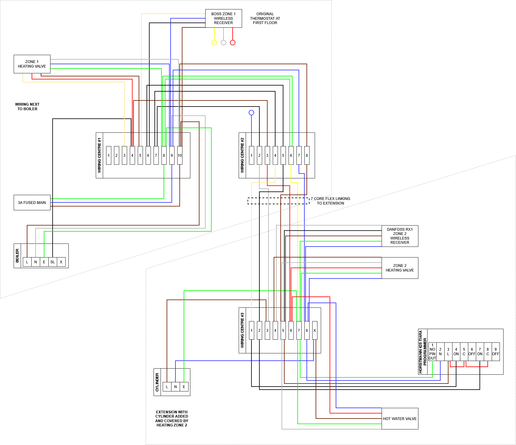
I believe if the system had been a simple S plan system with 2 zones with the wiring all neatly as expected I probably would have been able to get to grips with it but with the ad-hoc nature of the wiring I am somewhat struggling to get my head around how it is operating and how/where I need to intervene to remove the existing heating controls and replace them with the Drayton Wiser system.
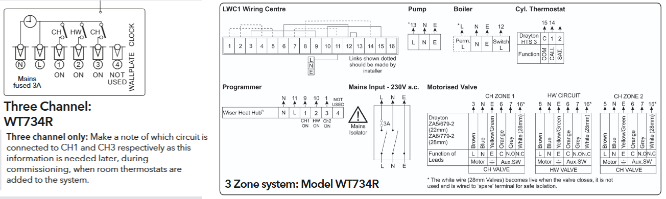
Drayton Wiser wiring:
Any assistance would be much appreciated. I am ready and able to provide any further information on the existing system that may be required.
Thanking you in advance.
Our heating system is in need of update and I have purchased a Drayton Wiser Thermostat Kit 3 system (WT734R) with the hopes of being able to carry out the installation myself. However, I turn to you requesting some advice on untangling the complex wiring system that appears to have developed over the life of the house's heating system.
Some background on the system as far as I am aware. It's ~100yo house and at some point the old cold feed tank was taken out when the loft was done and a pressurised system installed being an Ideal Logic+ System 30. There was one heating zone and and the wired thermostat was replaced to be controlled by a Boss Therm BRTRF wireless thermostat and BR1 receiver. Approx. 20 years ago an extension was added and a new cylinder was installed in the extension (Vaillant VIH GB 210S) along with a new heating zone controlled by a Danfoss RX1 wireless thermostat covering the extension areas. This was paired with a Horstmann 425 Tiara programmer also installed alongside the new cylinder. In order to make the link with the new elements of the system within the extension it appears a second wiring centre was installed linked to a third wiring centre in the extension via a 7 core flex.
The heating system has always had issues, particularly in controlling it, wherein at the height of summer, with no apparent demand for heating, the radiators in the extension would be red hot with no way to turn them off via the thermostats. Now the rotating dial to set the temperature on the Boss thermostat has completely fallen off (it was connected via a piece of plastic no more than 1mm diameter so a miracle it survived this long) and is stuck at 4 degrees!
I have mapped the existing wiring layout which is represented in the following diagram.
I believe if the system had been a simple S plan system with 2 zones with the wiring all neatly as expected I probably would have been able to get to grips with it but with the ad-hoc nature of the wiring I am somewhat struggling to get my head around how it is operating and how/where I need to intervene to remove the existing heating controls and replace them with the Drayton Wiser system.
Drayton Wiser wiring:
Any assistance would be much appreciated. I am ready and able to provide any further information on the existing system that may be required.
Thanking you in advance.
Last edited:


