Electrical wiring diagram for boiler system

Joined
11 Feb 2025
Messages
4
Reaction score
1
Country
United Kingdom
Hi,

Hope everyone is well!

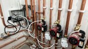
I am REALLY in need of some assistance. I knew this day would come haha. So basically I have been doing an electrical installation in a house for a relative and the plumber has finished his side and ready to test. Upon going up thinking there would be a diagram left with the system he installed, there is no.

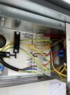
Is anyone able to help me connect this system correctly? I will be purchasing a 3 channel time clock and 2 stats (which are wired) for the system. And for the boiler I have LNE and a permanent feed from the control box also. Everything has been put into the control box.

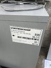
Please see attached photos and do not hesitate to help!

Many thanks,
 

Attachments

  • IMG_7770.jpeg
    IMG_7770.jpeg
    237.2 KB · Views: 77
  • IMG_7767.jpeg
    IMG_7767.jpeg
    281.7 KB · Views: 75
  • IMG_7743.jpeg
    IMG_7743.jpeg
    250.9 KB · Views: 66
I look at pictures, and the first question has to be, why three pumps? I also have two pumps, the problem is motorised valves only have a single pole micro switch in them, the normal way is for the thermostat/hub to turn on the motorised valve, and then the valve turns on the boiler and pump.

However, with one boiler and two pumps, only way is a relay, so the motorised valve works relay, then one set of contacts in relay works the pump, and the other the boiler, so the is no back feed making the other pumps work.

The idea is, the motorised valve must be open before a pump runs, one can plumb the by-pass valve so if a microswitch sticks, the by-pass valve opens, and micro switches do stick.

I know underfloor heating often uses a control box with loads of relays in it, but I used oct base relays in an adaptable box, in my case same boiler works main house and flat. I started with the diagram below.
C_Plan_My_HouseD.jpg
I did this before the plumbers had finished, I had expected only one pump once finished, this did not work, as both pumps would always run, so added relays, the new diagram is on a PC needing repair, so can't get it at moment, and also only got around to fitting on relay, as flat hardly used. Second one is on my to do list.

My boiler is running C Plan, the pictures don't really tell me much.
 
Thank both of you for your replies! All that the plumber left me was which pump was which. Zone 1, zone 2 & hot water. I will also google this thank you.
 
The Grant vortex is electrical a very simple boiler just requires live neutral and earth.
3 pumps plus 3 motorised valves is well different unless you have a low loss header?
If pumps are intended to work independently that's going to need some relays.
 
Okay thank you for the knowledge! I will ask the plumber who installed it if they need to work independently. And if there is a low loss header in the installation.
 
Just off the phone to him. He has the first pump on the left that comes on with the boiler. The other two pumps are independent for each zone due to the size of the runs. He would like them to come on with the motorised values when the zone is called. Is this possible?? Many thanks!
 

If you need to find a tradesperson to get your job done, please try our local search below, or if you are doing it yourself you can find suppliers local to you.

Select the supplier or trade you require, enter your location to begin your search.


Are you a trade or supplier? You can create your listing free at DIYnot Local

 
Back
Top