Erbauer table saw wiring diagram

Joined
5 May 2008
Messages
14
Reaction score
0
Country
United Kingdom
I have a 220 volt single phase table saw with a magnetic switch. There was some suspicion that the switch was faulty as it would start but not run. This happened once before and I cleaned dust from the magnetic switch part and it was OK. I repeated the process and it was OK for a while, then same again. I am ordering another switch but in the meantime a guy who was helping me out was convinced it could be wired "direct" and swapped the wires around, now it just trips the main circuit.
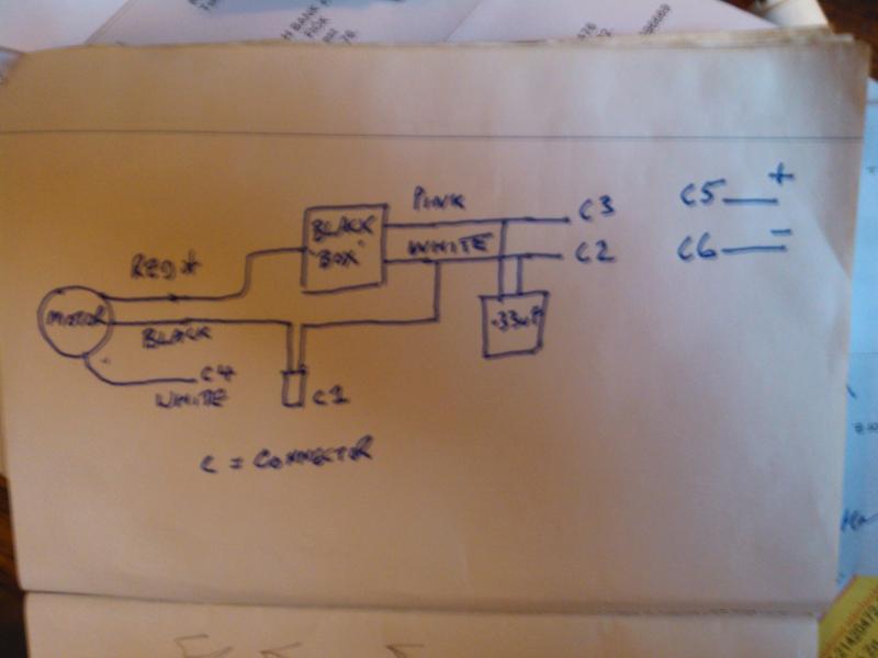
I am not an electrician but understand that there is a starter circuit and a main circuit which explains the 3 wires (+earth) coming from the motor BUT they are interconnected with a large black box (no markings) and a yellow box (marked .33uF).
First I would like to know how to connect it up, but second what componenet is doing what and why - I would like to understand a little of what I am doing.
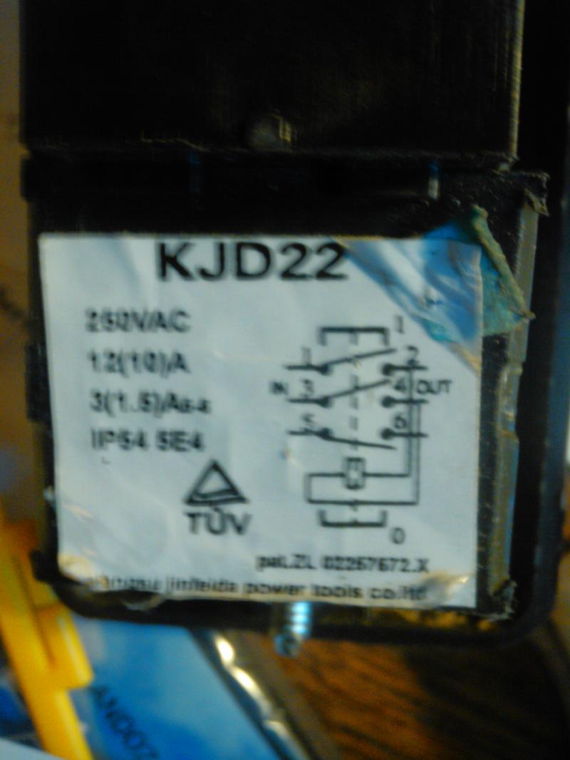
I have uploaded a wiring diagram and the switch diagram...Help!
PS on the switch, what is the connection between terminal 2 and 4
 
Sponsored Links
What voltage is used in hungary
you would be better posting in the other forum rather than the uk forum
 
Could not find your reply, just the photos. Do I need to add anymore info?
 
Sponsored Links
220 volts, close enough to UK. Have used the saw for 9 years
 
Unfortunately although diagram shown is one way there are many ways to get a single phase motor with two windings to start. Some have capacitor in circuit all the time and some have timers and/or centrifugal switches which remove the supply to second winding once running.

The idea is two fold one it increases the power to get it started and two it makes the motor rotate in the correct direction.

So you need the wiring diagram for your motor not just any motor.
 
I did look for the starter for Flyght Pumps as the old 2 inch single phase pump had a remote starter with capacitor and thermal start device but it would seem today these have been replaced with inverters.

I do remember struggling where an electrician swapped two wires thinking it was going in wrong direction, but is was single phase not three phase, and the windings were near same resistance, and it would seemed I guessed wrong, and got start and run windings wrong way around, which although it ran for a while in the end burn its self out. Seem to remember I expected start to be higher resistance to run but with that motor it was the other way around.

There is no one diagram fits all it must be the one for your motor.
 
PS on the switch, what is the connection between terminal 2 and 4

I may be wrong but it looks to me that its double pole switching

1+3 are L+N supply in
2+4 are L+N supply out to load

The thing shown wired between 2+4 represents the load
the thing marked uf i would suspect to be a capaciter

capaciters are sometimes parralel across L+N supply for Power Facter correction.
Also capaciters can be used with motors in series with windings
 
OK a little closer, it amazes me that there is no diagram out there ( and boy have I searched) for an erbauer or rexon table. Just found out Draper uses the same switch so will hunt there.
If anyone else has any more thoughts....
 
More info about this MAGNETIC switch may help, is this in the moter or somewhere else, where is it on the drawing.

Also what is your drawing, is that something youve copied from what you have or something from the internet.

What is this C1, C2 etc on the drawing are they the connections to the switch.
what was altered on this magnetic switch is it on the drawing

what do you mean by starts but dont run

Sorry for the questions but it all appears a bit confusing
 
Thanks for coming back, answers below:
More info about this MAGNETIC switch may help, is this in the moter or somewhere else, where is it on the drawing.

It the on off switch, the printed picture is the circuit diagram from the switch.
The drawing is the wiring as it exists now

Also what is your drawing, is that something youve copied from what you have or something from the internet.

It is my drawing

What is this C1, C2 etc on the drawing are they the connections to the switch.

Yes, C1 C2 etc are the connections

what was altered on this magnetic switch is it on the drawing

The switch has not been altered, just the connections were changed without a note of where they were originally

what do you mean by starts but dont run

The motor starts, comes up to speed, but as soon as the on button is released it stops

Basically, I am trying to work out which of my "C" connections fit to the termianls on the switch diagram
 
I had not realised this was your picture. From what you say you are missing the hold on contacts. The diagram shows the coil wired across the output but it does not show what is used to switch it off again. Some times the off button presses on the overload reset other times it's hard wired. Same with the on button some times a small switch and some time to presses on a contact on the contactor.

Try some photos of inside the box. You say it runs but will not keep running so some where either a stop contact is not closing or a hold on contact is not making all what I said about capacitors etc can be forgotten.

I though flyingsparks was showing you who to wire it up not showing the pictures you had missed off the post.
 
thanks for this, I have ordered a new switch just in case it is the problem, the challenge will be which cable to connect to which terminal!
 
Ok right,
Am i correct the thing you altered is the connections on the KJD22

The drawing is AFTER you moved certain wires on the KJD22


What do you mean by C5+ and C6- shown on your drawing

Is this KJD22 a pushbutton on switch, still not sure what you mean by MAGNETIC

How do you turn the unit OFF

As eric says it seems like the hold in circuit has failed and terms C5 and C6 may be part of that function, its also possible its a form of safety circuit holding off maybe a sensor preventing access to the blade
Edit

Is this what you have
http://www.thetoolboxshop.com/kjd22-magnetic-power-tools-stop-button-switch-8549.html

If so that thing in the diagram wired across 2 and 4 looks like the contacter coil of the switch assembly
 

DIYnot Local

Staff member

If you need to find a tradesperson to get your job done, please try our local search below, or if you are doing it yourself you can find suppliers local to you.

Select the supplier or trade you require, enter your location to begin your search.


Are you a trade or supplier? You can create your listing free at DIYnot Local

 
Sponsored Links
Back
Top