Before I ask the question its best you guys know some details:
About Me:
I’m a 25 year old IT technician who has had no experience of any electrical installations previous to the one I am currently doing. I have copies of BS 7671:2001 and BS 7671:2001 (2004) which I’ve been reading through over the past few months.
The Project:
I bought a 1950’s ex council flat back in March which had surface mounted cabling/accessories and existing vulcanised cabling left in walls and ceilings. I’m about half way through doing a complete reinstall of the entire electrical system.
Current Situation:
I have pulled down all the ceilings and removed all the existing cabling and accessories.
I’ve cut channels in walls/plaster and notches in the reinforced concrete beams above old ceiling for cable runs.
I’ve fitted all knock out boxes to walls and have run most of the cabling for power, lighting, TV, network and supplementary earth bonding.
I’m currently getting ready for the first fix inspection to be done by an electrical contractor on behalf of the council to get my work approved. I have been in regular contact with the contractor through the installation to make sure Im complying with the regs.
Question:
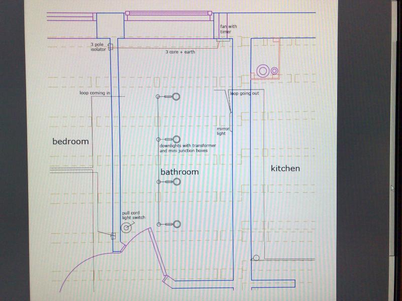
I have 4 12v down lights (plus 4 small junction boxes) that I will be putting in the bathroom and also have a fan with a timer. I will have a pull cord light switch inside the bathroom and a 3 pole isolator on the other side of the bathroom wall in one of the bedrooms.
I want the fan to turn on with the lights and to remain on for 15 minutes or so after the lights have been turned off.
I’d like to know how to connect everything up so that it will work the way I want it to. At the moment I have some 4 core cable going from the fan location to a box on the other side of the bathroom wall which will hold the isolator. I also have the cables from the lighting ring coming in both sides of the room.
Thanks in advance for any help guys!

About Me:
I’m a 25 year old IT technician who has had no experience of any electrical installations previous to the one I am currently doing. I have copies of BS 7671:2001 and BS 7671:2001 (2004) which I’ve been reading through over the past few months.
The Project:
I bought a 1950’s ex council flat back in March which had surface mounted cabling/accessories and existing vulcanised cabling left in walls and ceilings. I’m about half way through doing a complete reinstall of the entire electrical system.
Current Situation:
I have pulled down all the ceilings and removed all the existing cabling and accessories.
I’ve cut channels in walls/plaster and notches in the reinforced concrete beams above old ceiling for cable runs.
I’ve fitted all knock out boxes to walls and have run most of the cabling for power, lighting, TV, network and supplementary earth bonding.
I’m currently getting ready for the first fix inspection to be done by an electrical contractor on behalf of the council to get my work approved. I have been in regular contact with the contractor through the installation to make sure Im complying with the regs.
Question:
I have 4 12v down lights (plus 4 small junction boxes) that I will be putting in the bathroom and also have a fan with a timer. I will have a pull cord light switch inside the bathroom and a 3 pole isolator on the other side of the bathroom wall in one of the bedrooms.
I want the fan to turn on with the lights and to remain on for 15 minutes or so after the lights have been turned off.
I’d like to know how to connect everything up so that it will work the way I want it to. At the moment I have some 4 core cable going from the fan location to a box on the other side of the bathroom wall which will hold the isolator. I also have the cables from the lighting ring coming in both sides of the room.
Thanks in advance for any help guys!