Good Morning all,
Just a bit of reassurance required,
I'm happy when it comes to CC wiring on alarms, but trying FSL for the first time so please be gentle!
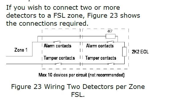
Followed various diagrams provided online, and resistors that come with my alarm panel (scantronic 9752)...
I have run wires to multiple windows from the control panel, which will be wired up as one zone... I.e, two contacts, with separate wires running to the control panel (in case i want to split it later), but as one zone now.
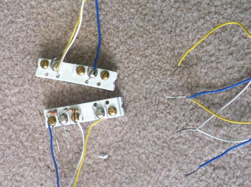
So i did a test wire as attached:
Can someone eye ball it and let me know if it looks ok or have i missed something?
I will check resistance when i actually wire up but going with the resistors provided at present.
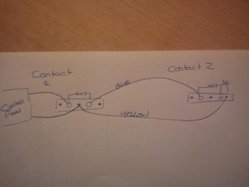
Blue and Yellow on the right are for the zone, blue and yellow twisted will be soldered and heat shrunk in the control panel as will the white.
On the top contact, both resistors, blue from zone goes to the 2.2k tamper resistor, output from that to the input for reed, and also to the 4k resistor. the output from the 4k resistor goes back through the white to the control panel, and back to the second contact into the reed OUT for the second contact.
The output for the first contact reed goes via the control panel and into the in for the second reed.
The out for the second reed along with the white returns back to the second connector for the zone on the control panel...
Hopefully the picture makes the above description clearer!
Pic:
I tried to check it with the multimeter i have, but it wont measure anything above 1k ohm so useless. Looking to get a new one later so test this if need be!
Look forward to a response!
Just a bit of reassurance required,
I'm happy when it comes to CC wiring on alarms, but trying FSL for the first time so please be gentle!
Followed various diagrams provided online, and resistors that come with my alarm panel (scantronic 9752)...
I have run wires to multiple windows from the control panel, which will be wired up as one zone... I.e, two contacts, with separate wires running to the control panel (in case i want to split it later), but as one zone now.
So i did a test wire as attached:
Can someone eye ball it and let me know if it looks ok or have i missed something?
I will check resistance when i actually wire up but going with the resistors provided at present.
Blue and Yellow on the right are for the zone, blue and yellow twisted will be soldered and heat shrunk in the control panel as will the white.
On the top contact, both resistors, blue from zone goes to the 2.2k tamper resistor, output from that to the input for reed, and also to the 4k resistor. the output from the 4k resistor goes back through the white to the control panel, and back to the second contact into the reed OUT for the second contact.
The output for the first contact reed goes via the control panel and into the in for the second reed.
The out for the second reed along with the white returns back to the second connector for the zone on the control panel...
Hopefully the picture makes the above description clearer!
Pic:
I tried to check it with the multimeter i have, but it wont measure anything above 1k ohm so useless. Looking to get a new one later so test this if need be!
Look forward to a response!