Galaxy Flex Internal Sounder

Joined
7 Feb 2017
Messages
1
Reaction score
0
Country
United Kingdom
Hello,

Help would be appreciated:

Manual states for the internal sounder:
Connect load (8–32 ) between OP3 and +12 V

Which sounds easy enough.

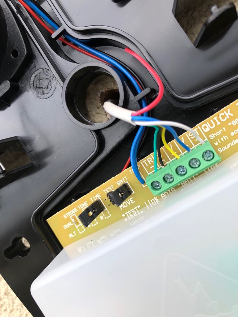
However on the panel, where the outputs reside I see 5 connectors:
OP1 OP2 OP3 T- 0v

The OP3 is obvious, but none of these strike me as being +12v.
I did think about using +12v from the intellibus or the sensors but wasnt sure hence thought it safer to ask.

Thanks

Simon
 
Sponsored Links
The Vertical (keypad ) +12V and the 3x horizontal (Zones) +12V connections are all connected to the same power rail on the Flex.
 
Sponsored Links
My external bell box which is a Honeywell ag6 does not work either. All it has is a red light illuminated on it.

This is how I wired it.
Tamper to T
ST to OP2
S to OP1
V+ to 12v on sensors
V- to 0v.

Do I need to enable something in the menus?
 
Take the op1 from its terminal and temporary connect to 0v. If the sounder sounds then the bellbox is fine. Put the wire back and perform bell test and measure between op1 and 12v. It should measure 12v. If not, load panel defaults menu 51.17 and try again.

Was the panel bought new ?
 
Yes purchased new. I will try this tomorrow and let you know what the results are.
 
Tried it and it doesn't sound it. Tried connecting bell directly and it works when i connect it directly to 0v and 12v. But doesnt via op1. So confused. Why do alarms have to be so complicated?
 
It's not complicated, just simple electronics. You don't confirm if you followed my instruction by only moving the trigger from op1 to zero volts??? Connecting the bell to 12v and ground does not confirm that the trigger circuit is working.

The output should be pulled to zero volts when the alarm is triggered. The programming does this from defaults with op1, so a new panel should be set to do this. Just to confirm that to test the output you are selecting 'Test -> Outputs -> Bell and setting to on. Try placing the bell trigger in op2 and testing the strobe to see if the siren will sound then.
 
Tried moving the trigger which I guess is op1 to 0v and nothing changed. I am testing on menu 32 and bell output which is 1001.
 
If the op1 to zero volts did not trigger the siren, then it's probably the siren at fault. Can you post a pic of the panel wiring to the sounder.

If the siren has 12v and 0v on its supply and the siren tamper switch is closed, then attaching the bell trigger to 0v should sound the siren.
 
60123114-C30A-4C36-BBC6-DBE70E45F012.jpeg


This is the wiring. I am taking 12v from sensors. My AG6 is connected as per instructions to OP1 and OP2. OP3 is my internal siren which is SP20ST.
 
Also using a multi meter, I get 11v on OP1, 13v on OP2 and OP3. I should also note that the sensors also give out 13v. Strangely I get only 3v at the other end of the internal sounder wiring and 4v when i set this to test. I can't get up to the bell box on the wall outside to test that end but I would imagine the wiring should be ok.
 
The green tamper wire looks a different shade. Is there a join somewhere? Your colour code is a bit confusing as supply is normally black and red. If no join, it all looks correct. What do you mean by internal sounder - a speaker to op3 and +12v?

When you talk of these voltages they are in respect to what ? One lead on 0v and the other on the different terminals? With the bell test ON and one lead on 0v what does the other lead on 0p 1 measure?


No join. Same wire. Someone else got on a ladder and did the other end of the wiring so i just matched it up on the panel end to the appropriate points.

I have an internal Honeywell SP20ST sounder https://www.security.honeywell.com/uk/products/intruder/alarm-communications/sounders/524172.html

This goes into OP3 and 12v. It only has two wires.

The voltages measured on OP1 and 0v measure 11v with bell test off and 12.5v with the test on.
 

DIYnot Local

Staff member

If you need to find a tradesperson to get your job done, please try our local search below, or if you are doing it yourself you can find suppliers local to you.

Select the supplier or trade you require, enter your location to begin your search.


Are you a trade or supplier? You can create your listing free at DIYnot Local

 
Sponsored Links
Back
Top