Hello
I have a Galaxy G2-20 and an LCE-01-4 ethernet module to make use of ethernet functionality with an iPhone. Before connecting it up I wanted to check a few things.
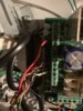
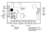
Enclosed is a picture of my Galaxy G2-20. It has a C020-01-C PCB with a Mk7 keypad and V2 wireless receiver connected. Currently the keypad and V2 wireless receiver wires are joined and are connected to the PCB as follows
2 Black leads (-)
2 Red leads (+)
2 Green leads (A)
2 White leads (B)
My questions are as follows:
Question 1
From what I can see the panel does not have a RS485 bus header. Is this correct?
Question 2
Assuming there is no RS485 bus header I was going to connect the ethernet module using flying leads
on the panel screw terminals. The ethernet momdule has a Red (+12V), Black (0V), White (A) and Yellow (B) leads.
Am I correct in connecting the leads so that there are now three leads joined and connected as follows?
2 Black leads (-) + Black (0V)
2 Red leads (+) + Red (+12V)
2 Green leads (A) + White (A)
2 White leads (B) + Yellow (B)
Question 3
In the image of the G2-20 PCB there appears to be two 12V Auxilliary outputs. One is currently being used for the keypad and wireless receiver.
What is the second one for? Can I connect the ethernet Black (OV) to the other auxilliary output (-), ethernet Red (12V) to the other auxilliary output (+) instead?
Or is it better to join the power wires to the existing ones as suggested in Question 2.
Question 4
In the image of the G2-20 PCB there is a 2-way header RS485 termination. What is this for?
Best regards
Embee
I have a Galaxy G2-20 and an LCE-01-4 ethernet module to make use of ethernet functionality with an iPhone. Before connecting it up I wanted to check a few things.
Enclosed is a picture of my Galaxy G2-20. It has a C020-01-C PCB with a Mk7 keypad and V2 wireless receiver connected. Currently the keypad and V2 wireless receiver wires are joined and are connected to the PCB as follows
2 Black leads (-)
2 Red leads (+)
2 Green leads (A)
2 White leads (B)
My questions are as follows:
Question 1
From what I can see the panel does not have a RS485 bus header. Is this correct?
Question 2
Assuming there is no RS485 bus header I was going to connect the ethernet module using flying leads
on the panel screw terminals. The ethernet momdule has a Red (+12V), Black (0V), White (A) and Yellow (B) leads.
Am I correct in connecting the leads so that there are now three leads joined and connected as follows?
2 Black leads (-) + Black (0V)
2 Red leads (+) + Red (+12V)
2 Green leads (A) + White (A)
2 White leads (B) + Yellow (B)
Question 3
In the image of the G2-20 PCB there appears to be two 12V Auxilliary outputs. One is currently being used for the keypad and wireless receiver.
What is the second one for? Can I connect the ethernet Black (OV) to the other auxilliary output (-), ethernet Red (12V) to the other auxilliary output (+) instead?
Or is it better to join the power wires to the existing ones as suggested in Question 2.
Question 4
In the image of the G2-20 PCB there is a 2-way header RS485 termination. What is this for?
Best regards
Embee