Generator earthing

Joined
31 Mar 2006
Messages
20,027
Reaction score
1,391
Location
Leeds
Country
United Kingdom
Hello chaps.

Been doing a bit of reading up on this, but I'm still after a bit of clarification for what is best to do.

I have a customer who has a BIG TP&N generator in his workshop next to his house.

It was installed to supply his (commercial) workshop with 3 phase as he lives out in the sticks and the DNO wanted a small fortune for a TP supply.

Recently there have been some problems wth the power round there. He was without power for nearly 24 hours last weekend due to a tree falling on his 11kV line.

So, the plan is to take a cable from the generator in his workshop to his main CU. (The workshop is fed from here), and connect it through a 2 pole chanegeover switch. The hose CU is only SP.

Now the bit I'm unsure about. How should the generator be earthed? I read that it should have a stake driven in near the generator, and this should be connected to the generator frame, and also be used to tie the generator neutral to earth.

I have also seen some information about linking the neutral and earth pins in the socket for the generator to input into the changeover switch. I presume this is only required for portable generators which are not staked to earth?

I presume that providing the gen set is properly staked down that RCDs will function properly?

I don't know how the generator is currently configured as it was dark while I was round there tonight, but I want to make sure it's right before I take it on.

Oh and it is all on a farm if this makes any difference to what earthing arrangements can be used.

The DNO supply is TN-S fed from it's its own dedicated 11kV - 230V pole pig.

Sorry for all the questions, but this is a little outside the scope of my normal works.
 
Sponsored Links
Make sure the changeover switch switches the neutral. This is expecially important when mixing earthing systems such as TN-S supply and TN-C-S gen. Many older automatic changeovers where only TP and not N.

Is this a hard wired set, or does it have a plug? Assuming hard wired it is likely to already have a link from N to E/frame which is visible in the alternators marshalling box. It may not be visible, but certainly measureable.

Staking down is important to prevent floating earths, and nice low impedance would obviously be good! I prefer earth tapes to rods, especially if you are trenching anyway. Whack in a length of 50 or 70mm hard bare drawn copper cable. This size is specced by the DNO for tail ends on PME supplies and also for earthing subs etc (the days of mesh is long gone). We have always gone this route, mainly because my boss was DNO trained.
 
I normally sub-contract this sort of thing to a generator company as it is also out of my usual scope. I would have thought that the gen is already earthed TT-style with a rod? And that there is 230v in the workshop?

There wouldn't be a problem in connecting the gen earth to your house MET, and the PH & N via a 2-pole changeover switch, so that's easy enough. I suppose the important bit is ensuring that the earthing system of the gen allows minimum disconnection times. 100mA RCD I suppose... Sorry, I'm not giving you any answers, just joining in, as I have a job coming up which may be similar - TNCS on a farm with backup genny. With new-builds drying up, I may have to refine my knowledge somewhat! :confused:
 
Sponsored Links
The regs can seem a little ambiguous on the subject of final circuit protection. If the generator is 'permanant' then the 30mA requirement is not required (disregarding other requirements for 30mA protection) although you will have to check the EFLI of the final circuits if no RCDs are present. It makes an interesting point actually, as you are changing the characteristics of the supply with a generator are you then responsible for the installation (ie bringing it up to current regs)
Back to the generator - there must be no floating earth. One side of the output winding must be bonded to the frame and earth to create an earthed Neutral. Also if there is any IT equipment in the house it can be a good idea to make sure the generator has automatic voltage regulation so as not to send any nasties down the supply.
As said above make sure the C/O switch for the SP supply is double pole otherwise you will create a Neutral to Earth fault with the generator link when the house is on mains. Also the RECs tend not to like 'energised Neutrals' when working on supply faults!
 
I have read with interest the comments:-
1) Household applications and similar are not covered by the AGRICULTURAL AND HORTICULTURAL PREMISES section. See 705.1
2) Although a TN-C system can’t be used. See 705.411.4 and without a metal grid a TN-C-S supply is not recommended see 705.415.2.1 Note there is nothing to stop the use of a TN-C-S supply.
3) There is a need for a single point of isolation see 705.537.2 this may limit type of change over used.
4) The RCD requirements are a little different 32 amp instead of 20 amp ceiling for sockets requiring RCD at 30ma and all sockets at 100ma and everything else at 300ma.
5) Most large generators of around 750KVA have variable RCD’s which need to be inaccessible to ordinary persons it may be prudent to change these for a type which ordinary persons can access.
6) Small generators of around 65KVA often have an option for zig zag wiring to use in single phase mode and do not like any unbalanced loads. Also often the AVR is only connected to a single phase and if the wrong phase is selected do not regulate very well. Two cures A) run a three phase motor to help balance. B) Use an inverter.
7) Large generators with turbo do not like running light load and you may need to provide a method of adding a load bank.
8) The earth is in the main not a problem with large generators on farms with the metal grids laid under cow sheds etc. But these can’t be tested with an earth loop impedance tested a proper earth meter with to two moveable spikes is required which may incur extra expense if you need to hire one.
Different people have a different idea of BIG. I worked on some BIG generators in Suffolk (2 x 750MW) and Flintshire (4 x 600MW) but before that I considered the 12 x 750 KVA generators were BIG which considering the Suffolk generators had a number of 1.5MW generators as standby to ensure all pumps continued to run made the 750KVA ones look small. I have not linked generators under 250KVA normally the small one don’t have syncroscopes to allow one to parallel them up.
Some small generators even up to 7.5KVA have no electronic AVR and can be really unsuitable to run any voltage dependent equipment.
Only the 1.5MW and above were 3.3KV or more although the 12 x 750KVA had 9 step up and step down transformers and I knew every last nut and bolt on the 7.5KVA generators but in spite of spending 4 years involved with the BIG generators I only learn some very small areas of the whole. The 400MW units had a 180KW fixed magnet generator at the back just to power the lub oil pumps.
So let’s have a little more information as to size of the unit.
 
Now the bit I'm unsure about. How should the generator be earthed? I read that it should have a stake driven in near the generator, and this should be connected to the generator frame, and also be used to tie the generator neutral to earth.
Check with the manufacturer or have a look at the actual genny - I think that a generator of that size may already have the N-E linked.
What you need to do is provide the means of earthing i.e. the same as what the DNO do at the supply transformer to create a Terra system. The DNO need to make sure that the resistance between their spike and earth is less than 21ohms which is the max figure I'd aim for. Slight problem for you - you can't use an EFLI tester to check this as this is the initial link and you need 2 for a circuit! The proper way to test the electrode is to use an earth electrode resistance tester (Method 1 in GN3).

I have also seen some information about linking the neutral and earth pins in the socket for the generator to input into the changeover switch. I presume this is only required for portable generators which are not staked to earth?
The purpose of linking neutral to earth is to create the Terra system, without this link the supply would have no reference to earth hence there is the possibility on a 3 phase genny of having an undetected first fault and a second fault resulting in 400v being aparrent between a phase and earth. However as I said above I think this link may already be in however you'd still need to check.
I presume that providing the gen set is properly staked down that RCDs will function properly?
Yep - staked down and the star point tied to earth.
 
Well I know it's been a while, but I was back at the farm today.

I have checked out the generator a bit more closely. It seems there is a N-E link fitted at the generator, and the frame is bonded.

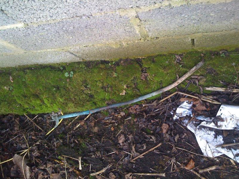
There is also a 16.0mm² from the generator to an earth stake.

Now there is the problem.

This is the earth stake


DIYnot Local

Staff member

If you need to find a tradesperson to get your job done, please try our local search below, or if you are doing it yourself you can find suppliers local to you.

Select the supplier or trade you require, enter your location to begin your search.


Are you a trade or supplier? You can create your listing free at DIYnot Local

 
Sponsored Links
Back
Top