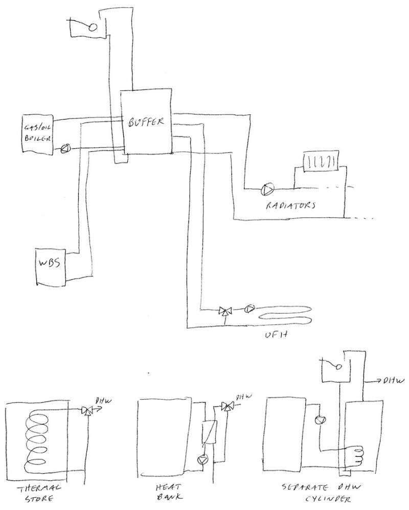
Here's a suggestion of what I believe you should aim for.
Note that the wood burner has a simple convection circuit to the buffer - no valves, no pumps, just natural convection. There
may be a requirement for some valves (thermostatic vale on the hot flow ?) to avoid the WBS running too cold - I'll leave the experts to debate that one. Also not shown is any form of heat dump, which could just be a thermostatic valve and a radiator on a convection circuit - again the experts can advise on that.
Note the TMV on the UFH - without it you'll overheat the system.
The rads can be all TRV if you fit a modulating pump. This works very nicely and will give you a quiet system. EDIT: No need for a bypass at all - just let the modulating pump back off as the TRVs close.
For DHW you have a number of options as shown at the bottom of the drawing.
On some of the circuits, there may be a need for a check valve. Not so much to stop reverse flows, but just to avoid convection circulation when you don't want it. That will depend heavily on the layout - eg if the buffer tank is low down (like the thermal store in the garage underneath my flat) then the rad circuit will readily thermosyphon.
The position of the tappings is roughly as I'd probably do them - although I should have drawn the CH takeoff below the level of the heat imputs (ie the boiler and WBS should go in higher up). The heat sources go in part way from the top so that if they are supplying water at lower than the buffer temperature (as the boiler in particular may do when starting up) it will leave some hot in the top for the benefit of the DHW - particularly important with a heat bank or thermal store.
The rads come off highest up as they want the warmest water, then the UFH. The UFH return will generally be warmer than that from the rads - hence the rads returning to the bottom of the buffer and the UFH a bit higher up.
So the heat sources supply hot water, then the various loads take a bite before it's eventually drawn out cool from the bottom to be reheated - if set up right it will certainly help in keeping the boiler in condensing mode.