

Hi
I'm having some difficulties with my heating. The CH will not work unless HW is also called for. I've had british gas out twice (on contract) to look at it, and twice they changed the powerhead on the Honeywell diverter valve in the airing cupboard. This seems to fix the problem but then it intermittently returns.
I thought before I call them out a third time I'd try to understand this myself. However despite some DIY electrical knowledge, these electrics seem more complex and are not obvious to me, and I can't find a diagram online that looks like it might fit my heating. Although my heating setup looks like a "Y plan" in terms of plumbing, the electrics don't match Y plan examples posted on most sites.
So, my heating/diverter problem aside...can anyone please explain to me how my heating circuit works? It doesn't help that I don't know where some of the wires come from, so maybe someone could shed some light?
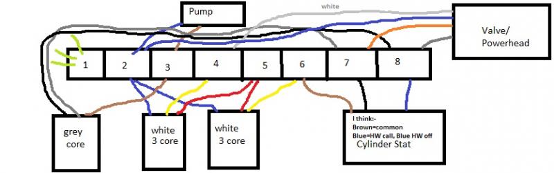
This is a sketch of the junction box in the airing cupboard:
Finally - I made a few measurements with the multimeter. I'd assumed all of this was some kind of glorifed set of switches in series. But I'm not just reading 0 or 240v, I'm also seeing 130v and 50v.. etc. what's going on!?")
[edit - to add these details]
* Potterton Suprima HE boiler
* Potterton EP 2000 programmer unit - black box with CH and HW slides, allows HW and no CH, or HW and CH (sliders mechanically limited). PERMANENTLY SET TO 24 hrs CH and HW because room stat has a programmer in it.
* Heatmiser root stat acting as a volt-free switch (self installed - swapped from honeywell dial stat - I think this problem independent of that but not 100% sure, another reason to check wiring before calling out british gas again). I guess that's at the end of one of those white 3 core wires?
* p.s. sorry typo on the diagram I think for the cylinder state its black for HW call (not blue as noted), and blue for HW not called, with brown common.
I'm having some difficulties with my heating. The CH will not work unless HW is also called for. I've had british gas out twice (on contract) to look at it, and twice they changed the powerhead on the Honeywell diverter valve in the airing cupboard. This seems to fix the problem but then it intermittently returns.
I thought before I call them out a third time I'd try to understand this myself. However despite some DIY electrical knowledge, these electrics seem more complex and are not obvious to me, and I can't find a diagram online that looks like it might fit my heating. Although my heating setup looks like a "Y plan" in terms of plumbing, the electrics don't match Y plan examples posted on most sites.
So, my heating/diverter problem aside...can anyone please explain to me how my heating circuit works? It doesn't help that I don't know where some of the wires come from, so maybe someone could shed some light?
This is a sketch of the junction box in the airing cupboard:
Finally - I made a few measurements with the multimeter. I'd assumed all of this was some kind of glorifed set of switches in series. But I'm not just reading 0 or 240v, I'm also seeing 130v and 50v.. etc. what's going on!?
[edit - to add these details]
* Potterton Suprima HE boiler
* Potterton EP 2000 programmer unit - black box with CH and HW slides, allows HW and no CH, or HW and CH (sliders mechanically limited). PERMANENTLY SET TO 24 hrs CH and HW because room stat has a programmer in it.
* Heatmiser root stat acting as a volt-free switch (self installed - swapped from honeywell dial stat - I think this problem independent of that but not 100% sure, another reason to check wiring before calling out british gas again). I guess that's at the end of one of those white 3 core wires?
* p.s. sorry typo on the diagram I think for the cylinder state its black for HW call (not blue as noted), and blue for HW not called, with brown common.
