Hive Mini Installation

Joined
21 Nov 2023
Messages
7
Reaction score
3
Country
United Kingdom
I have recently purchased a Hive Mini Kit for a dual zone central heating system that will be used with a Potterton Promax boiler. I have bought the Hub, 2 receivers and 2 thermostats. My intention is to replace the Centaurstat 7 programmers that are currently installed in the hall and main bedroom with the 2 single channel Hive receivers and then fit the thermostats nearby.
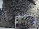
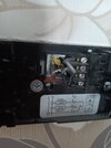
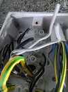
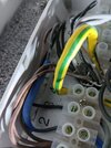
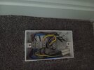
I opened the upstairs programmer and this is the wiring configuration. I am unsure as to how to wire the Hive receivers once I remove the original programmer. Any help would be really appreciated.
 

Attachments

  • centaurstat7.jpg
    centaurstat7.jpg
    176.9 KB · Views: 76
Sponsored Links
It's not entirely clear from your photo, but it appears that brown is connected to terminal 1, black to 2 and grey to the unused terminal 4.
Is that correct?

For the Hive Mini to work, it will require a Neutral connection.
The good news is that the grey wire could be used.
The bad news, we don't know what the grey wire is connected to at the other end.
Have you a wiring centre? Can you trace this cable back to it?
 
Hi

Thank you for getting back to me.

You are correct, brown is connected to Terminal 1 and black is connected to Terminal 2. The Grey wire is connected to Terminal 4 and although very unclear in the picture there is an "N" embossed in the plastic slightly above the number 4.

I have traced the cable back to what I think is the Zone Valve controller for the upstairs heating. This box has 3 cables entering it, two of these cables are 4 core and the grey wires have been snipped and are not connected to the chocolate box strip. The third cable is I think the power supply to the controller and has blue sleeving on it and is attached to the chocolate box.

I am reasonably confident that the grey cable with the blue sleeving does not go to the programmer that is currently fitted. My logic behind this is the outer insulation is grey whilst the cable that supplies the current controller is white. I do not understand though why both grey wires have been clipped but one of these is connected to the Neutral terminal in the current programmer.

I have attached two pictures that hopefully should clarify the above, however it is a bit of a snake pit and I can take more if anything is not clear.

Thanks again for taking the time to look at my post and offering advice,

Steve
 

Attachments

  • Cupboard 2.jpg
    Cupboard 2.jpg
    242.2 KB · Views: 43
  • Cupboard1.jpg
    Cupboard1.jpg
    219.5 KB · Views: 43
I do not understand though why both grey wires have been clipped but one of these is connected to the Neutral terminal in the current programmer.
Many posters on here have found similar.
It can be considered good practice to incorporate a cable with enough wires for a mains powered thermostat. However, as a battery powered thermostat has been installed, there is no need for a neutral connection, along with any possibility of faults/shorts, had it actually been connected.

Yes, it is likely that the snipped greys need to be connected to a neutral at the wiring centre, but I'd prefer a couple more photos to confirm!

Could you post a slightly wider pic that cover the whole box?
 
Sponsored Links
Thanks again for the response.

I've taken a picture of the box and also the flex cable that joins both of the controllers together and then another picture to show how they are joined to the zone valves.

The grey wires from the flex are connected to the chocolate box strip, but the only grey wire that is connected is the one from the cable with the blue sleeving, and I don't believe that is the cable going to the current programmer ion the main bedroom.

Steve
 

Attachments

  • cupboard 3.jpg
    cupboard 3.jpg
    236.5 KB · Views: 46
  • cupboard 4.jpg
    cupboard 4.jpg
    179.4 KB · Views: 41
  • cupboard 5.jpg
    cupboard 5.jpg
    180.3 KB · Views: 44
I've taken a picture of the box and also the flex cable that joins both of the controllers together and then another picture to show how they are joined to the zone valves.
Great, thank you.
I was expecting to see some connections to the zone valves, but didn't see what I was expecting.
It makes sense now, that those are in a different box!
Could we see inside that one as well please? :)
 
This is the box nearest the zone valves.

Hopefully the clarity of the photo is ok, the light bounces back of the wires and the colour, in some instances, is not that well defined.

No problems taking some more if required.


Many thanks

Steve
 

Attachments

  • cupboard 6.jpg
    cupboard 6.jpg
    699.8 KB · Views: 39
Thanks again for the photos, that confirms it :)

The grey cut off wires are the grey wires appearing at your existing controllers - they will need to be connected to the neutral at terminal 2 of the wiring centre.

There are three grey cables coming up through the middle of the box. These are the two cables to the controllers and a cable back to the boiler (including a switched live (call for heat) on terminal 3).

The two black wires connected to terminals 7 & 8 are the switched lives returning from the controllers. These drive the zone valves.
When these are in position, a microswitch in the head will provide a switched live back to terminal 3.

So...
At the wiring centre, strip and connect the two greys to N at terminal 2

At the controller, brown goes to L on the single channel Hive
Grey to N
Black to terminal 3
Additionally, add a short link wire between L and terminal 1
 
Thank you very much for the clear instructions. I will be installing the Hive receivers first thing in the morning and let you know how I get on.

I will do the upstairs first, and then test everything is ok before doing the downstairs.

By connecting the 2 grey wires to Terminal 2, will it cause any issues to the original downstairs thermostat before I change it for the Hive receiver?

Many thanks again

Steve
 
By connecting the 2 grey wires to Terminal 2, will it cause any issues to the original downstairs thermostat before I change it for the Hive receiver?
As long as the grey is also wired into the spare terminal 4, then there shouldn't be a problem.

good luck :)
 

DIYnot Local

Staff member

If you need to find a tradesperson to get your job done, please try our local search below, or if you are doing it yourself you can find suppliers local to you.

Select the supplier or trade you require, enter your location to begin your search.


Are you a trade or supplier? You can create your listing free at DIYnot Local

 
Sponsored Links
Back
Top