Hive multizone on C plan. Zone 2 not operating hot water

Joined
23 Apr 2012
Messages
31
Reaction score
0
Location
Dumfriesshire
Country
United Kingdom
Hello,

I’ve recently replaced a bit of a hybrid controller system on my old c plan ideal Mexico floor standing boiler. It all operated fine but wanted to make programming a bit simpler.

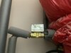
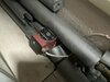
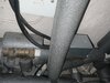
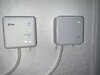
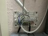
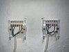
I have an c plan system with gravity hot water and pumped heating. There is a zone value on the hot water along with a tank thermostat and I have two central heating zones. I have a dual hive receiver set to gravity mode and a single receiver for the other heating zone upstairs.
It works as expected on the main two channel receiver in gravity mode, I.e. hot water turns on/off and when I activate the central heating on it turns on the heating with the hot water when I want CH, all fine.

BUT when you turn on the 2nd heating zone via the other single channel receiver this opens the zone valve for upstairs heating and activates the pump but doesn’t fire the boiler or the hot water.?

What am I missing. How do you get the 2nd single channel reviver to know it’s paired to a gravity mode dual channel receiver. Or should I be adding another wire somewhere to connect the 2nd heating ON to the HW?

it seems that the hive system just doesn’t know the 2nd reviver should fire up the HW when it’s turned on.

So in order to get heating from the 2nd zone via the single channel receiver I must manually ensure the HW is on.

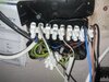
there are no connections from the heating zone valves i.e. on the micro switch to the boiler. This was managed via the old hortsman programmer previously and now via the hive. I thought the hive would be clever enough to tell the 1st receiver that when the 2nd receiver wanted heating it would tell the 1st to turn on the water but no.

I must be missing a connection somewhere to activate the HW and boiler when the 2nd receive calls for heat and operates the zone valve. Wasn’t sure though if you wire that to the boiler or back to the HW in the 1st hive receiver?

help greatly appreciated and I hope this makes sense.
 
Sponsored Links
Picture of your HW cyl, I dont think you have a gravity HW system, I think you are getting mixed up between gravity HW and open vent, try setting your hive to fully pumped
 
Bit of a mission to explain but I’ll post some pics then add some comments. But there is definitely NO pump on DHW circuit. It’s gravity from flow and return on boiler. The CH circuit is from different pipes from boiler and is pumped. It’s open vent too if that helps.

it’s a bit complicated due to two separate wiring centres as the heating zone valves were added after the main install. Anyway I’ll post pics then add comments once is see how it looks on post.
 

Attachments

  • C3390A70-ABEA-425E-B5BF-CA7D82288E3C.jpeg
    C3390A70-ABEA-425E-B5BF-CA7D82288E3C.jpeg
    174.6 KB · Views: 64
  • 43C20309-C966-46CB-AC60-6DC1396B9C2E.jpeg
    43C20309-C966-46CB-AC60-6DC1396B9C2E.jpeg
    215.9 KB · Views: 66
  • 381F1E7B-7291-441D-99FA-1A6C6FF89091.jpeg
    381F1E7B-7291-441D-99FA-1A6C6FF89091.jpeg
    299.6 KB · Views: 62
  • 8725AC6B-647F-4A36-ADBC-A55EF59F3116.jpeg
    8725AC6B-647F-4A36-ADBC-A55EF59F3116.jpeg
    358.4 KB · Views: 85
  • A2CC2B49-477B-4CC9-BF00-4A1798E9037A.jpeg
    A2CC2B49-477B-4CC9-BF00-4A1798E9037A.jpeg
    198.5 KB · Views: 82
  • 3D5961E3-BAF0-49D1-A8D0-29BEA10E7481.jpeg
    3D5961E3-BAF0-49D1-A8D0-29BEA10E7481.jpeg
    251.4 KB · Views: 73
  • C31BB450-013A-4505-B48C-AFD526A4C1B3.jpeg
    C31BB450-013A-4505-B48C-AFD526A4C1B3.jpeg
    260.4 KB · Views: 76
  • 31408C58-7CB7-41FD-BAC4-FE574E81D59C.jpeg
    31408C58-7CB7-41FD-BAC4-FE574E81D59C.jpeg
    286.5 KB · Views: 83
Last edited:
Sponsored Links
The first picture is the cylinder stat. 2nd is the DHW zone valve. 3 is the heating pump. 4 one of the heating zone valves, the other is out of view. 6 the new hive receivers. 7 wiring centre that connects the heating zone valves. 8 the two hives, showing the wiring. 9 main wiring centre.

I’ll try my best to explain how things are connected next…
 
Main wiring centre - the messy one

1. Cylinder stat, DHW zone valve
2. Hot water on from Hive (1st receiver, no. 3 connection), boiler, cylinder stat
3. Neutral for boiler, DHW zone valve, CH pump
4. Na
5. CH pump (switched), connection to each CH zone valve. 5 and 7 in other wiring centre, connected to orange zone valve cables.
6. Na
7. Neutral. Hive receivers and heating zone valves in other wiring centre.
8. Live. Hive receivers and zone valves via other wiring centre.

other wiring centre, the white one.

1 live
2 neutral
3 earths
4 heating on from 2nd hive, connected to upstairs zone valve brown wire
5 connected to 5 in other wiring centre I.e pump.
6 heating on from first hive, connected to downstairs zone valve brown wire
7 connected to 5 in other wiring centre, I.e. pump.

The 1st hive receiver is the dual channel hive. It operates fine, hot water and heating. The 2nd hive single channel receiver works but will not fire boiler.

I suspect I need to link this somewhere but don’t want to guess! If I had to guess, link the an output from the upstairs zone valve to No.2 on main wiring centre, so when value opens it sends power to that terminal which fires boiler?
 
Last edited:
That's a mess!
Attached pics for C plan and S plan plus maybe start again?
 

Attachments

  • 20211108_232606.jpg
    20211108_232606.jpg
    204.4 KB · Views: 69
  • 20211108_232538.jpg
    20211108_232538.jpg
    244.1 KB · Views: 88
Thanks for the wiring diagrams. System was inherited years ago, works so I’ve just left it be. Only issue now, apart from mess! Is the fact zone 2 will not fire boiler. Rewire may be a job for Sunday.

is it an Open Vented System with Gravity Fed Hot Water?


Right, I may need to re post but I’ve been operating under some wrong assumptions for over a decade since moving to our house. Well, I think!

Our boiler, ideal Mexico cf 125, has 4 water pipes, 2 for the HW and 2 for CH. the CH is pumped and the HW circulates via gravity, controlled by a zone valve and cylinder stat. When we moved in there was a really old analogue type controller, rotary type thing. This was replaced with a hortsman 2 channel controller. This was connected in gravity mode. It was then further added to by installing 2 wireless room stats controlling two heating zones. So when the hortsman CH was on, the wireless room stats controlled the CH on/off.

The hortsman and wireless room stats have now been replaced with Hives.

Questions

If there was no zone valves on my heating could this be a C plan? I think the answer is yes? essentially my system matches the C plan. (But the wiring isn’t c plan, yet…)

Can a C plan independently control HW and CH? I think that due to the way my system was wired all those years ago I was the reason it’s been controlled as “Gravity” and my wrong assumption carried forward about what it should and can do. I.e. the heating can’t be on separately from HW.

if the answers to the above are yes, I can rewire as C plan, and insert the heating zone valves between wiring centre 9 and the CH pump live.

according to the boiler manual,

WATER CIRCULATION SYSTEM
The boiler is suitable for connection to pumped open vent
central heating systems, pumped central heating combined with
pumped or gravity indirect domestic hot water supply systems
and gravity or pumped indirect domestic hot water supply
systems.
The boiler is NOT suitable for gravity heating systems.

So mine is I believe pumped open vent CH with indirect gravity HW.

Anyway, thoughts welcome. I could be barking up the wrong tree.
 
Clear pictures of boiler and it's pipework - pump - all pipework around cylinder if you have 2 separate heating zones you should have a zone valve controlling each one.
 
You are up late!

Difficult to get clear pics due to boiler location but please see attached. The pipe work at the rear of the boiler you will hopefully see the 4 water pipes. The water cylinder is above the boiler and the flow and return pipes connect to the cylinder via the 2 port zone valve. This is not pumped.

The other two pipes are CH, pump on the return. There are two zone valves on the CH. One for down and one up stairs.

Many thanks for your continued help. Your C plan schematics were most helpful.
 

Attachments

  • 20211109_230602.jpg
    20211109_230602.jpg
    179 KB · Views: 118
  • 20211109_230613.jpg
    20211109_230613.jpg
    270.1 KB · Views: 74
  • 20211109_230648.jpg
    20211109_230648.jpg
    148 KB · Views: 57
  • 20211109_230714.jpg
    20211109_230714.jpg
    232.5 KB · Views: 74
  • 20211109_230739.jpg
    20211109_230739.jpg
    192.4 KB · Views: 61
I would have thought it would need a relay, I had the same using Nest Gen 3 with thermo syphon DHW and two pumps and two motorised valves on the CH, there is no way to fire the boiler and open the motorised valve when you want CH and not have the DHW also open motorised valve without using relays.
 
Hello. Yes the expansion pipe connects to the system and heads on up to the attic space, up there is the CH header tank and the main stored water tank that has a feed to the cylinder I.e. cold water in.

Eric - I saw that issue with nest and the work around with relays. I’m sure though I saw a work around post documenting how to do it without a relay. It was partly why I discounted Nest as it wasn’t clear if it natively supported Gravity.

anyway, I’m not sure I have that issue. If I can rewire to standard C plan and assuming separate controls it may work without relay. I guess a relay would do the trick for me know though but I want to identify if I can migrate to c plan with independent hw an ch controls first.
 

DIYnot Local

Staff member

If you need to find a tradesperson to get your job done, please try our local search below, or if you are doing it yourself you can find suppliers local to you.

Select the supplier or trade you require, enter your location to begin your search.


Are you a trade or supplier? You can create your listing free at DIYnot Local

 
Sponsored Links
Back
Top