Hive multizone on C plan. Zone 2 not operating hot water

other wiring centre, the white one.

7 connected to 5 in other wiring centre, I.e. pump.

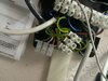
Yet there appear to be two wires in 7, I assume that the black wire is the one that goes to 5 in the other wiring centre (ie the pump) but there is another brown/red wire that looks like a link to 5, which you say also goes to the pump. Is that correct? After reading the description of the other wiring centre terminal 5 I think it is but it just seems strange someone has added a link to duplicate wiring already in place.

Capture.JPG


I think @ericmark is on the right lines, with fully pumped systems all motorised valves will start both the pump and boiler, in your case the heating should start the pump and boiler, but the hot water only the boiler. So some isolation is needed between the pump and boiler, i.e. they can't be connected together as it would be impossible to have one on without the other.

EDIT
Also, the black (messy) wiring centre you describe as having 8 terminals; the photo shows 9. Looking at it, there seem to be two vacant terminals which would be 6 & 7 in the photo, you only mention 6 being vacant, so I suspect what you describe as 7 and 8 are really 8 and 9. :confused:

If above assumptions are correct, I reckon:

1. Hive 1 is set up as gravity HW pumped CH and is controlling the boiler accordingly. The only connection to the boiler is terminal 2 of the messy wiring centre that is powered by the HW on from Hive 1 and nowhere else.

2. Hive 2 is wired to the downstairs motorised valve and its orange wire energises the pump via messy wiring centre 5. It has no connection to the boiler. So, unless the Hot water is on at Hive 1 to start the boiler the downstairs heating won't work.

If the orange wire from the downstairs motorised valve was wired to a relay with two contacts instead, then one contact wired to the boiler and one to the pump that would allow the downstairs heating to control the boiler and the pump, with the relay providing the required isolation between the two items.

I also have some concerns:

1. The hot water cylinder thermostat will close the HW motorised valve when the hot water cylinder is hot, but the boiler will stay on while ever the Hive 1 HW remains on. So unless the heating is operating there is nowhere for the water to circulate. I'm a sparky not a boiler expert so that maybe ok with your type of boiler.

2. The orientation of the pump. Usually they have bearings that are water lubricated and should be mounted with the shaft in certain axes (i.e. horizontal). Yours isn't. It appears to be mounted with the shaft vertical like the one on the bottom left below, with a red X though it.

pump.JPG


ee.JPG
 
Last edited:
Sponsored Links
In truth the best option is a bit of a re pipe and turn the cylinder feeds into fully pumped .
With you layout relative easy to do then you get advantage of much faster heat up time on hot water (and more energy efficient) and cures wiring issues at a stroke system becomes S plan plus.
 
Hi stem- many thanks.

the picture is poor, in 7 there is only a single black wire, the grey one goes to 6!

messy wiring centre - 1 isn’t empty, it’s as per description but there are two empty ones, 6 and 7. So 7 and 8 are actually 8 and 9 but the wires to them are as per description

assumptions

1 yes
2 yes. A relay would work here I think

concerns

1 yes. But it’s been like that for over 12 years, so assume it’s OK!
2 yes. Though again, I’ve been here for over 12 years and it’s been ok
 
Exedon, again thanks for support.

probably agree S plan would be good but in truth we have never had any real issue with the cylinder taking too long to heat up. It’s one of those, where if it’s working leave it be.

however, the controls I have tried to modernise have highlighted a bit of a unique wiring set up and you have indicated a C plan would be the way to go, if no major work to fully pump.

am I right to say the C plan wiring would allow independent hw and ch controls. That’s what the wiring looks like. I have all the relevant cables on my hw zone valve, they just are not used. See pic.

if changing to c plan does what I think and eliminates a relay, I think that’s a good first step. Then come spring I can consider anything more drastic.

can anyone just confirm C plan does independent hw and ch?
 

Attachments

  • image.jpg
    image.jpg
    276.9 KB · Views: 46
Sponsored Links
C plan was always intended to use only one zone valve (the hot water one) could not install it now not to building regs.
I just think trying to make some sort of hybrid wiring system which will certainly involve relays as in standard S plan pump and boiler always linked together could very easily take much longer and not cost much less than what would be easy pipework modification.
 
C Plan was designed to provide independent control of the heating and hot water. However, to achieve that, the C Plan 2 Port motorised valve has an additional white control wire (shown in black below) This is wired to a switch inside the valve that will keep the boiler going for the heating, when there's no demand for hot water. Most 2 Port motorised valves don't have this, so unless yours has, you would have to change the hot water motorised valve.

cp.gif


@Exedon is right, the best way would definitely be to modify it to an S Plan+ it's not a massive modification, it will provide totally independent control of the all three parts of your system, resolve the pump position, heat the hot water faster, and be more economical. At the moment at certain times the boiler will keep cycling unnecessarily just to keep itself hot when there's no demand. And the wiring can be made safe and done properly at the same time.

The work will have to be done if the boiler is replaced in the future at some point anyway. Unless you're hoping it will last until we all are forced to have heat pumps and then everything changes. :)
 
This whole thing started a few months ago when I looked at heat pumps, bio mass etc to get rid of gas. Long story but nothing other than gas (or hydrogen) will currently heat my home. I then got quotes for a new gas boiler, issue being due to pipe length from mains and size of boiler needed, domestic gas engineers will not touch it, commercial grade job. I reckon I’m reliant on gas until 10 plus years brings us hydrogen!

anyway, thanks all for input. My plan is two pronged.

As my hot water zone valve has the white wire, three control ones in total, they are just made safe in a terminal block. No idea why it was never done as a C plan all those years back…

1. upgrade to c plan wiring. From my PoV it looks like a straightforward task. It appears to me I could insert both zone valves for the heating to activate terminal 5 in the C plan wiring. This should eliminate the req. for relays? PLEASE if I’m being a numpty and relays still required shout! But would the orange wire from ch zone salve not go live when the CH on from my Hive activates and when connected to terminal 5 activate the pump?

2. come spring commission a plumber to upgrade to S plan +. As you say, effectively blank of the current hw ports from boiler, connect in the heating circuit via a 3 port valve, sort wiring, job done. Prob put a new pump head on when at it.

I’ll report back on progress.

many thanks stem and exedon
 
You can wire it up as a C Plan with the white wire connected to the pump as per the diagram below and the orange wire to the boiler L. Note: this is the only wire that should go to the boiler L. The wire from terminal 2 of the "messy" box that goes to the boiler can be removed and connected to the orange, if convenient.

The grey needs to go to a permanent live.

Each of the two room thermostats is wired to operate its associated motorised valve. [The live to the thermostat comes from the appropriate Hive, then goes to the motorised valve brown wire] I think this is as it is now.

Heating motorised valve grey wires should go to a permanent live and from your description it sounds like they already do.

The orange wires from both heating motorised valves connect to the pump at the point shown in the red circle below instead of the wire/s from the room thermostat/s which now go to their associated motorised valve. And again it appears that they already do.

cp.gif
 
Last edited:
Just a quick update. Converted to C plan with the heating zone valves connected to 5 as above. All now working as I hoped, hives both working (set to fully pumped) and I have independent CH and HW controls. Thanks all.
 

DIYnot Local

Staff member

If you need to find a tradesperson to get your job done, please try our local search below, or if you are doing it yourself you can find suppliers local to you.

Select the supplier or trade you require, enter your location to begin your search.


Are you a trade or supplier? You can create your listing free at DIYnot Local

 
Sponsored Links
Back
Top