Hello all, I’m hoping that someone can help please, as I’m at a complete loss.
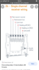
I’m installing a Hive Single receiver to my Glow Worm Extramax Combi boiler and have got to the final stage on wiring up the actual receiver to the boiler. The 240v (L&N) are connected and the system is powered and synced, but I just can’t figure out where the ‘common’ and ‘heating on’ wire go on the boiler panel. This is 1 and 3 on the actual Hive receiver.
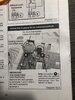
I originally thought they would go into the voltage free connectors (E) on the instruction manual picture attached, so I removed the link and wired up the common and heating on. I then removed the original remote thermostat wires from the neighbouring connections (F), but it then showed an error code.
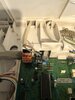
I have attached a photo of the actual board and the connectors and also the section out of the instruction manual.
The one with the link (E) is the ‘voltage free’ and the one next (F) is the current remote thermostat. Having done some further research, is it actually just a case of removing the wires from the current thermostat (F) and replace them with the hive wires. If that’s the case does it matter what way they go into the terminals.
Can someone advise if I’m on the right track please or can anyone tell me where the actual common and heating on wires actually go.
Any assistance really appreciated.
Thanks all.
I’m installing a Hive Single receiver to my Glow Worm Extramax Combi boiler and have got to the final stage on wiring up the actual receiver to the boiler. The 240v (L&N) are connected and the system is powered and synced, but I just can’t figure out where the ‘common’ and ‘heating on’ wire go on the boiler panel. This is 1 and 3 on the actual Hive receiver.
I originally thought they would go into the voltage free connectors (E) on the instruction manual picture attached, so I removed the link and wired up the common and heating on. I then removed the original remote thermostat wires from the neighbouring connections (F), but it then showed an error code.
I have attached a photo of the actual board and the connectors and also the section out of the instruction manual.
The one with the link (E) is the ‘voltage free’ and the one next (F) is the current remote thermostat. Having done some further research, is it actually just a case of removing the wires from the current thermostat (F) and replace them with the hive wires. If that’s the case does it matter what way they go into the terminals.
Can someone advise if I’m on the right track please or can anyone tell me where the actual common and heating on wires actually go.
Any assistance really appreciated.
Thanks all.