Hive wiring for a logic 30 Combi

Joined
20 Nov 2017
Messages
5
Reaction score
0
Country
United Kingdom
Hi guys, please can you offer me some advice. Purchased the Hive single channel with the idea in mind of a "simple" swap with my current timer.
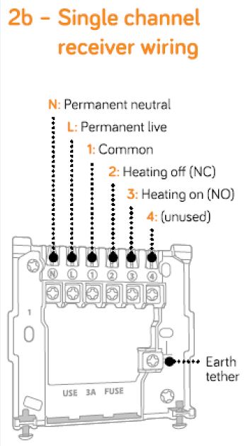
After looking at the installation manual it looks like I may need a rewire from the boiler as I'm missing the common. Does that look about right to you? I like to know what I'm talking about calling up a sparky. Cheers
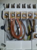
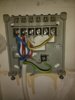
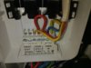
capture-jpg.130387

Current set up is:
 

Attachments

  • IMG_20171117_171404494.jpg
    IMG_20171117_171404494.jpg
    166.1 KB · Views: 8,556
  • IMG_20171117_215127513.jpg
    IMG_20171117_215127513.jpg
    134.3 KB · Views: 13,603
Last edited:
Sponsored Links
Your system is slightly unusual in that the 230V mains comes into the thermostat rather than the boiler. It's not a problem just different to most. Based on your photos, this is how I see your installation now. If this is not correct, post back what you do have.

Now.jpg

If the above is correct then the existing wiring is OK for the single channel Hive and would be installed as below:

With Hive.jpg

Note the subtle shift of the yellow wire to terminal 3 (Heating On) at the Hive
The red link at the boiler end is not necessary so you can remove it (you don't need it now BTW, but it isn't doing anything) leave the other wires exactly as they are.
A link is required at the Hive between L & 1

If you have an existing room thermostat somewhere that must be decommissioned to prevent it interfering with the operation of the Hive. It cannot simply be disconnected otherwise the heating control wiring will be 'open circuit' and the heating will never come on. This means that the existing thermostat switching wires will need to be bridged out by connecting them together at the wiring centre or some other convenient point.
 
Hi stem, thanks for your detailed response. Yes you're correct with your first diagram, the wiring into the thermostat/timer is where the boiler is spurred, it looks a bit dodgy tbh, have you seen that before? We have no other thermostat so we're all good there.

So basically remove link in boiler, for Hive make link between L & 1 and shift yellow from 4 to 3.
 
So basically remove link in boiler, for Hive make link between L & 1 and shift yellow from 4 to 3.

Yep, that's it.
the wiring into the thermostat/timer is where the boiler is spurred, it looks a bit dodgy tbh, have you seen that before?

It's not good wiring, but I've seen worse. Anyway, it can easily be tidied up when the Hive is installed. The copper conductors should be under the terminals and not exposed, and the bare earth wire needs some earth sleeving sliding on it. The main 230V supply should come from a switched supply via a 3A fuse. (which it probably does already)

Also, the incoming mains cable at the bottom doesn't seem to be secured at all, so the Live wiring terminal seems to be taking the strain. The cable sheath should really be fixed under a cable clamp, or at least in trunking or clipped to to wall to support it.

I'm guessing that the existing programmer was probably for a system with timed heating and hot water, but the hot water side wasn't necessary when the Combi was installed.
We have no other thermostat so we're all good there.

Not having an existing room thermostat greatly simplifies the installation of the Hive. Wiring an existing one out of the circuit is the bit where most folks come unstuck.
 
Sponsored Links
I'm guessing that the existing programmer was probably for a system with timed heating and hot water, but the hot water side wasn't necessary when the Combi was installed.

Yeah, I think you're right there. Cheers for all the info, ill be sure to get the clean up done and hopefully have the Hive up and running soon.
 
In my sketch I have shown three live wires in terminal (L) and only one live wire in terminal (1)

It will be easier to put the link between them, and then one of the other live wires in each. Electrically it achieves the same, but fitting two wires in each terminal will be easier than trying to cram three wires into one terminal.
 
Hi Stem Just wanted to let you know that the Hive was up and running. Advice was spot on so thanks for that. One thing I wanted to ask about though was the spur for the boiler/thermo was from the socket ring, is that ok? I expected it to have its own circuit.
 
Well done! glad to hear that it's working. :)

No problem with the way that it is connected to the ring circuit. Whilst 'new builds' may have a dedicated supply these days, the majority of boilers are connected to the ring circuit (including my own) The electrical requirement for a boiler is very small. The important thing is that the boiler has its own fused connection unit with a 3A fuse fitted.
 
Could you possibly help out with mine I have a logic combi 30 also . my mains goes into the boiler first.
I do have an existing room thermostat as well what steps need to be take to make this redundant so it doesn't interfere. Any help would be greatly appreciated.
20171209_133627.jpg
15128387643672098500479.jpg
 
Hi Scott and welcome to the forum. I only just spotted your post. For future reference it is best if you start your own new post rather than tag it on the end of someone else's, they can be easily missed. It is also called hijacking and is against the forum rules. Don't do it now, or you will have two threads going on the same topic.

So back to your question.

The wires you need to connect to the Hive receiver are all present at your existing thermostat, so remove the thermostat and relocate the wires to the Hive. From your photo:

Brown in terminal 1 is the 'live' wire. That goes to the Hive receiver live (L) terminal.
Grey in terminal 2 is the 'neutral' wire. That goes to the Hive receiver neutral (N) terminal
Black in terminal 3 is the 'Heating on' that goes to the Hive receiver Heating on (3) terminal
Then you add a link between the Hive (L) and common (1) terminals

You don't mention any time control for the heating, if you have a programmer somewhere, this will need to be set to be 'on' permanently, otherwise it will override the Hive.
 
Thanks for your prompt response. Sorry never used a forum site before.

Wired receiver up how you advised but when i turned power back on I don't seem to be getting any power to the reciver as no lights come on..

I do have a timer built into boiler but I have set to constant on as advised.

Thanks again for any further info
 

Attachments

  • 20171209_225657.jpg
    20171209_225657.jpg
    222 KB · Views: 2,877
They seem to go to the right places. You do have the single channel version of the Hive for combi boilers don't you?

And it was working OK before you started

And the wires aren't loose in the terminals

If the above is OK then check where the wires go at the other end of the thermostat cable.

Based on the diagram below from the logic 30 boiler manual

Capture.JPG

The Live Brown wire should go to L

The Neutral Grey wire should go to N

The black wire should go the the very end terminal of the terminal strip marked room stat / timer.

It is possible that the original thermostat was originally incorrectly installed and the Brown and Black wires are transposed. It would have worked but not as well as it should.

If that doesn't work, an alternative method of installation would be:

Wire the L, N & E of the boiler to L, N & E of the Hive.

Connect wires to the two boiler terminals marked room stat / timer. Connect one of them to terminal (1) common and the other to terminal (3) heating on. It doesn't matter which way around this time.

No links would be required in this instance, but you will need an additional wire.
 
Last edited:
Thanks again for ure reply mate.
Gonna try cables at thermostat with the multi meter try and find out why it's not powering the hive when connected.

If I wire hive into boiler like u suggest do I just leave old stat on or do I have to do something with those cables so it doesn't interfere?
 

DIYnot Local

Staff member

If you need to find a tradesperson to get your job done, please try our local search below, or if you are doing it yourself you can find suppliers local to you.

Select the supplier or trade you require, enter your location to begin your search.


Are you a trade or supplier? You can create your listing free at DIYnot Local

 
Sponsored Links
Back
Top