Glad you agree.Yes. ... Yes.
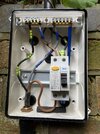
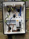
I would dare to suggest that, in conceptual terms, there are not really any other 'options'. To be consistent with all the observed facts, I would stick my neck out and say that the 'only' possibility that the conductor marked as E in the vicinity of the downstream MCB must be connected to the N side of the upstream RCD (regardless of how that end of the conductor is 'identified'). Is that not the case?Yes, it works. It is difficult to think of all the options.
Kind Regards, John