
You are using an out of date browser. It may not display this or other websites correctly.
You should upgrade or use an alternative browser.
You should upgrade or use an alternative browser.
How to wire texecom premier impaq plus to 24w panel
- Thread starter andriusv
- Start date

Do you want the reed and shock on seperate zones or on the same zone?
Page 31 of the Installation manual shows wiring. manual with panel either printed or on a CD.
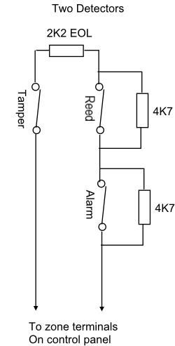
End of line (EOL) 1st picture of two.
If your still struggling get an alarm installer to complete this for you.
Its basically, 4k7 across the alarm, 4k7 across the reed, 2k2 as the end of line resistor. use double pole/eol wiring type (default wiring type on premier).
You can replace them all with 3k3 resistors if you wish. You should have a pack of 4k7, 2k2 and 3k3 resistors provided with the alarm panel.
If you did this normally closed, you would need to wire the alarm and reed in series back to the zone and the tamper into the auxiliary tamper circuit and program the zone wiring type as normally closed
Power goes to the auxilary power terminals.
Thank you for your help
I have attached photo of impaq and panel. I would be much apreciated if you can check it and point me to the right direction. Thank you
View media item 82739 View media item 82740
I have attached photo of impaq and panel. I would be much apreciated if you can check it and point me to the right direction. Thank you
View media item 82739 View media item 82740
at the moment you dont have the alarm linked to the reed.
or the 2k2 going from the reed to the tamper
and you have 4 wires excluding the power going back to the panel and you should have two.
This image was edited, originally it was two detectors, so there was another tamper, but in your case theresjust the one tamper, but two different sensors on the device that you are wiring.
Hi Andy,
look at the circles, these represnt the terminals.
4k7 across alarm
4k7 across reed
a wire to link one to the other as per the diagram (solid black line)
2k2 resistor from the reed to the tamper
A wire back to the panel zone from the alarm terminal
A wire back from the tamper to the panel zone
Unfortunately thats all there is to it. at the moment you need to loose 2 wires.
link the alarm to the reed and a 2k2 from the reed to tamper.
Do you have a spare zone ? To put the shock on a different one to the reed ?
Wants it on same zone i believe certainly simpler having them seperate.
did i got it right?
the reason i want on the same zone so i can arm front and back doors at night. the wired one is front door and i got wireless one on the back door so i want them on the same zone so i can arm just that zone or someting I understand it wrong.
View media item 82770
the reason i want on the same zone so i can arm front and back doors at night. the wired one is front door and i got wireless one on the back door so i want them on the same zone so i can arm just that zone or someting I understand it wrong.
View media item 82770
Try again !

It would be easier on a fault related issue to separate the two alarm sensors , you can use the existing 8 core cable ....
Have you programmed the panel yet as that will be fun for you !
It would be easier on a fault related issue to separate the two alarm sensors , you can use the existing 8 core cable ....
Have you programmed the panel yet as that will be fun for you !
okay you have the idea but unfortunatley its not right.
1 4k7 must go across the reed terminals R--4k7--R
1 4k7 must go across the alarm terminals A--4k7--A
1 alarm terminal needs linking to 1 reed terminal
-----R--4k7--R-----------A--4k7--A
the 2k2 resistor must have 1 leg in a tamper terminal and the other in 1 terminal of either the alarm or the reed.
-----R--2K2--T
-----A--2K2--T
do the above and then post your picture for the next step.
Then look at the diagram again and see if you can work out where the wires go back to panel zone.
It isnt the easiest thing to get your head round at first.
View media item 82778
done it again. is this right?
done it again. is this right?
DIYnot Local
Staff member
If you need to find a tradesperson to get your job done, please try our local search below, or if you are doing it yourself you can find suppliers local to you.
Select the supplier or trade you require, enter your location to begin your search.
Please select a service and enter a location to continue...
Are you a trade or supplier? You can create your listing free at DIYnot Local
Similar threads
- Replies
- 9
- Views
- 5K