how to wire under floor heating wiring center to Worcester boiler

Joined
25 Nov 2005
Messages
523
Reaction score
7
Country
United Kingdom
the under floor heating is controlled by wiring center. this wiring center get the order from wall thermostats when there is a demand for central heating. the wiring center in turn open the zone valve, switch on the plumb at the manifold and send a signal to the boiler to fire up. in the boiler section of the wiring center I connected the brown the the "com" terminal and and the blow to the "NO" terminal. the wiring center is also connected a a power supply and therefore it powers the wall thermostats, the (2 zone valve and the plumb) of the UFH manifold. Thus, it does not need to draw power from the boiler.

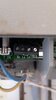
my question is where about inside the boiler I need to the brown and the blue wires the are coming from the wiring center. the boiler is Worcester 28cdi and the wiring block is attached.

can someone confirm if the below is correct please.
  1. to start with, i need to remove the link between Ls and the Lr, , ... correct?
  2. LS is the power supply form the boiler to the thermostat or in the case is my wiring center, if so, then this is not needed because the wiring center is already powered,
  3. if the above points are correct then all i need to do is connect the brown that is coming from the wiring center to the Lr of the boiler.
  4. And the blue that is coming from the wiring center to the Ns of the boiler.
 

Attachments

  • boiler connction.jpeg
    boiler connction.jpeg
    104.5 KB · Views: 219
Sponsored Links
Sounds about right to me:

Ls = "Live Supply" - Just a permanent live. It's there if you wish to use it (and presently handy for the link to Lr right next to it :))

Lr = "Live Return" - When this terminal is made live the boiler will run; usually as you say the control signal from the microswitch inside a motorised valve.
 
Whoa, hang on a minute ...
There are a number of things to be considered here.

Firstly, the wiring centre should have volt-free contacts for the boiler - you need to check what the individual wires are connected to before you connect the other end to the boiler. Assuming they are indeed connected to Common and NO of dry contacts, then that's fine.

At the boiler end you do NOT connect the blue wire to neutral. It is a blue wire, it is not a neutral wire - and in this setup will be a switched live wire. Based on the above, and bear in mind I've not looked at the manual, yes, you would remove the Ls-Lr link and connect the wires from the wiring centre to those terminals. You do need to check, and it varies by boiler - ours has low voltage stat connections and the manual is at pains to point out that if you connect "mains" to the thermostat terminals then it will destroy the control board.


There is something else to bear in mind. To comply with regs, the whole system must be fed from one isolator. Functionally it doesn't matter with the volt free (a.k.a.dry) contact setup here - but from a safety PoV it does. Several ways to handle this :
  • Take the feed for the UFH wiring centre from the same isolator (FCU) as the boiler
  • Split the feed with a junction box
  • Take the live and neutral from the boiler - need 3 wires (plus earth) to take live feed, switched return, neutral
  • Take the supply for the boiler from the wiring centre - potentially needs 4 wires (plus earth)
Which of these is easiest depends on where things are located, what wiring is already in place, and how easy it would be to run extra cabling if needed.
 
Sponsored Links
I have looked at a few UFH systems, and each one seems to have some thing different. As far as I am aware Worcester Bosch has not allowed one to electrical modulate the boiler unless you use their thermostats. So only control is on/off, but every time the boiler is switched off heat is lost out the flue, and also when switched on again it switches on at full output, so idea is to switch on/off as little as possible.

Some systems use just the boilers pump, but many have a second circulating pump and hot water is added as floor water cools, as said cable colours mean nothing specially with heating guys, lost count of number of times found a green/yellow wire with line voltage on it where some heating guy has tried to save on cores.

As @stem says it looks OK, but with out the control centre plan it is a guess.
 

DIYnot Local

Staff member

If you need to find a tradesperson to get your job done, please try our local search below, or if you are doing it yourself you can find suppliers local to you.

Select the supplier or trade you require, enter your location to begin your search.


Are you a trade or supplier? You can create your listing free at DIYnot Local

 
Back
Top