Ideal ESP1 with hive multizone

Joined
11 Oct 2018
Messages
20
Reaction score
0
Country
United Kingdom
hi all,

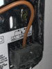
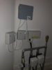
I have a question about hive, so to cut a long story short the boiler isn’t firing up when hive is kicking in.

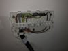
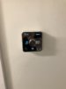
I have it wired so that the hive has the live neutral, connected, the common wire is connected to pin 1 on the hive bracket, and the n/o from the old thermostat is connected to pin 3.

Is there something I need to do to the boiler to get hive to fire it up? Or something on the receivers that I’ve missed?

Any suggestions on where to start looking would be great.

Thanks
 
Sponsored Links
Ok so to update, the hive is not pushing a call to service, there’s no power coming from pin 3 on the single channel receiver, could this be a fault with the hive? Or is there a setting I need to turn on or off?
 
If anyone has any suggestions on what to look for that would be great.

Thanks
 
First of all, no one has answered because you haven't given enough information to do so.

A Hive multizone provides control of several heating zones (eg upstairs and downstairs) so it will be replacing at least two or more room thermostats, but you refer to 'the thermostat' and 'the receiver'. Are you just converting one of them, or is this just because they are both identical?

If you can also provide details of the existing system to which you wish to add the Hive Multizone, you will stand a better chance of getting an answer. So:

1. What are the zones and how many are there?
2. What thermostat (make model) is presently controlling the temperature in each zone and how are they presently wired in.
3. If you don't currently have time control built in to each room thermostat (ie they are not programmable thermostats) what is providing the time control?
 
Sponsored Links
Hi Stem,

Apologies, the hives I have are replacing 2 wire (common and n/o) wired Danfoss thermostats, we have a EPH wiring centre in the upstairs closet next to the two valves which is where the two hive receivers are going.

The two thermostats which speak to the receivers are going upstairs and downstairs.

I’ve attached a pic of where it’s wired in to, I haven’t got a pic of the job done so far as I’m out of the country at the moment, but both valves are directly under this unit.

The boiler is a Combi Idel ESP1 38 if that’s any help as well?

Thanks and apologies for the lack of detail first time round.

Ian
 

Attachments

  • F8481695-E064-4618-9867-AEB2F8F31DE9.jpeg
    F8481695-E064-4618-9867-AEB2F8F31DE9.jpeg
    147.3 KB · Views: 384
OK thanks that helps a bit, but doesn't answer all of my questions, so I will assume:

As you have "receivers" that you actually have 'Wireless Thermostats' [The thermostats are wireless, the receivers are wired instead] and that when you refered to 'Wired Danfoss thermostats' below this is a mistake
the hives I have are replacing 2 wire (common and n/o) wired Danfoss thermostats

There should be three wires going from the junction box in your photo to each of the two existing thermostat receivers. As you didn't answer my question about time control I will assume that the thermostats also have the time control built in and that there isn't any separate time control elsewhere.

The easiest way would be to replace the two existing thermostat receivers with two Single Channel Hive receivers. Looking at your photo, I am assuming that there is a brown (L) & grey (N) wire from the wiring centre far left terminals that goes directly to each of the existing receivers L and N. There should also be a black wire coming back from each receiver, one zone will be in the far right terminal, and the other in the terminal next to it. If so the existing wiring at the receivers would connect as follows:

The Brown wire goes to the Hive receiver L
The Grey wire goes to the Hive receiver N
The Back wire goes to the Hive receiver 3 (Heating on)
Add a link between the Hive receiver terminals L and 1 (Common)

If in any doubt don't proceed, but ask for clarification. If you need any further help post the model number of the receiver and details of each wire and where it is connected.

You posted the boiler details in your posts title, but it is irrelevant with multizone as the Hive is wired to the motorised valves not the boiler.
 
Thanks Stem,

You have assumed correct on pretty much all points, the reason we are putting the receivers upstairs is because we don’t want both the receiver and thermostat where the previous thermostats were.

That being said, there were 3 wires where the thermostats were, however one wire was terminal led off leaving just two, I have attached a picture from that too.

Can I ask why I need to link wires L and 1? L is live and when the boiler comes on, point 1 is also live as well, is that a way of getting to work?

I will post the receiver details when I get back if needed but just curious about linking the points above that you mentioned.

Thanks

Ian
 

Attachments

  • B48910A3-CFEB-409E-907D-B37191AC0109.jpeg
    B48910A3-CFEB-409E-907D-B37191AC0109.jpeg
    244 KB · Views: 194
I can't see it clearly enough to see what it is, but that does looks like a wired thermostat not a receiver. In which case there would only be two wires used if it is battery powered. The Hive receivers aren't battery powered and need a 230V supply for them to operate hence the link, for the Live and the extra wire for the Neutral.

So, would I be right then in saying that the original set up (not the Hive) is that you have two battery powered wired thermostats without receivers that only have the brown and black wires connected.
 
OK, good. Now we are getting somewhere. The the grey wire is the N but is not used presently as the existing thermostats are battery powered. So, you can either remove the existing thermostats and put the Hive receivers in their place as I said before:
The Brown wire goes to the Hive receiver L
The Grey wire goes to the Hive receiver N
The Back wire goes to the Hive receiver 3 (Heating on)
Add a link between the Hive receiver terminals L and 1 (Common)

Or, if you don't want the receivers where the existing thermostats are located.

It is possible to disconnect the existing thermostat cables from the wiring centre. They will be the cables containing the black wires to the far right of the photo. You will have to work out which zone is which from the motorised valve they are connected to, and then wire in the Hives directly in their place as I've marked on the photo.

F8481695-E064-4618-9867-AEB2F8F31DE9.jpeg
 
Thanks Stem, I will do that when I get back, so what I have in place is the Live from EPH to hive L, the grey cable to neutral, but the Black cable next to earth, I believe that to be the common cable although I might be wrong, to port 1 on the hive, and the relevant cable on the right to port 3 on the hive, so it’s just a matter of adding the live cable to port 1 instead of the common cable to get the boiler to fire up?
 
so what I have in place is the Live from EPH to hive L
Yes that's the brown wire. Same for both Hives

the grey cable to neutral,
Yes correct. Same for both Hives

but the Black cable next to earth, I believe that to be the common cable although I might be wrong,
I have not mentioned that wire deliberately. Leave it well alone it has nothing to do with what you are trying to do.

It's the two black wires on the far right you are interested in. One will go to heating on (3) on one Hive and the other one will go to heating on (3) on the other the Hive.

Then add a link between L and 1 (Common). Same for both Hives.

EDIT:
Sometimes a picture helps, below is what you need to achieve. You will have to work out which motorised valve, and the Hive connected to it is upstairs and which is downstairs.
Drawing1 Model (1).jpg
 
Last edited:
Hi Stem,

That’s a massive help seeing it in a diagram. The only thing I can see that I have wrong is the common. I’ll remove it when I get home and link the live to it.

If this is all that needs to be done then I look forward to getting it working!

I’ll keep this thread updated and let you know the outcome.

Again a huge thank you for taking the time to asses what I needed, and I’ll be sure to add more detail next time!

Ian
 
Hi Stem,

Your advice was spot on! Hive is now up and running perfectly. I’ve attached a few pics of the (mostly) finished job.

Just need to do a bit of making good where the old thermostats were but other than that, it’s all good!

Thanks again for all your advice and help, it’s very much appreciated that you took the time with all your posts.

Thanks

Ian
 

Attachments

  • F57313A8-6827-4B67-91E3-02B33161EBE0.jpeg
    F57313A8-6827-4B67-91E3-02B33161EBE0.jpeg
    104.5 KB · Views: 252
  • 62EE28CC-5541-40DB-9678-BD8D2F264FBA.jpeg
    62EE28CC-5541-40DB-9678-BD8D2F264FBA.jpeg
    126.3 KB · Views: 173
  • 390B6644-8A27-481A-BC4B-470A369327A4.jpeg
    390B6644-8A27-481A-BC4B-470A369327A4.jpeg
    97.1 KB · Views: 174
Excellent news. Well done (y) and thanks for the update, it may help anyone that comes across this thread with a similar project.
 

DIYnot Local

Staff member

If you need to find a tradesperson to get your job done, please try our local search below, or if you are doing it yourself you can find suppliers local to you.

Select the supplier or trade you require, enter your location to begin your search.


Are you a trade or supplier? You can create your listing free at DIYnot Local

 
Sponsored Links
Back
Top