Impedance meter wiring

Joined
15 Nov 2011
Messages
15
Reaction score
0
Location
Suffolk
Country
United Kingdom
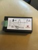
ok I have a Peacefair power meter with an impedance loop, a Chinese product and the wiring diagram is not clear,

The small loop appears to wire either way to the two middle terminals

Can anyone please explain if the loop goes over the live or neutral .. Sorry if it looks obvious but I'm not certain.. It looks like the neutral but ...

Thanks
 

Attachments

  • image.jpeg
    image.jpeg
    104.3 KB · Views: 107
Sponsored Links
I assume that the 'impedance loop' you are referring to is the coil which constitutes the 'current transformer' ("CT"). It should not really matter whether you put it on the line or neutral (since the same current will be flowing in both) but, conventionally, one would probably put it around the L.

Kind Regards, John
 
Hello John, thanks for replying, yes CT I mean will go on L that's great. what is confusing me is the diagram can be interpreted that L could be either side of load ..
Put the CT on Live load, the lowest screw in the block be N .. Is that too obvious that I'm confusing myself?
 
Hello John, thanks for replying, yes CT I mean will go on L that's great. what is confusing me is the diagram can be interpreted that L could be either side of load ..
As I said, the same current will flow in the conductors on either side of the load, so it doesn't really matter which one you put the CT on.
Put the CT on Live load, the lowest screw in the block be N .. Is that too obvious that I'm confusing myself?
Do you not have a wiring diagram? I'm not clear as to what those lower two terminals are for, but I assume that the top two go to 'the meter'. Do the bottom two also go to the meter, perhaps to supply power to it?

You should make sure that something is connected to those top two terminals before you put the CT around the cable (or, at least, before any current goes through that cable) - since potentially dangerous voltages could appear between those top two terminals if nothing was connected to them.

Kind Regards, John
 
Sponsored Links
It's not marked because it doesn't matter what way around L and N go, or what conductor the CT is put on. The unit will require some sort of fuse though and must be installed in an enclosure.
 
That's the only diagram and yes the two lower terminals will feed for back light and display
Thanks EtH I have enclosure but can't guarantee there's an internal fuse .. So will factor that in
One last thing, how a capillary thermostat works, must it be isolated from touching anything conductive and how does it send signal to the level setting knob? In stripping down and oven I snipped the wire due to access issues but once snipped .. Is it NFG?
There's a replacement coming tomorrow but would be good to know for future time ..
Thanks
Neal
 
It's busted, the 'wire' is actually a tiny pipe. Liquid and or gas (it was kerosene in the last one I cut apart) expands and causes a bellows to expand and contract at the control end.
 
I tip my hat to you both, and thanks again, I've googled about the stat and couldn't yet find any thing on it so that's great to know. The oven has a small pipe the bulb end fits into but being the dreaded Aga Im seeking to improve the layout and mostly succeeding for better monitoring and therefore control
Neal
 

DIYnot Local

Staff member

If you need to find a tradesperson to get your job done, please try our local search below, or if you are doing it yourself you can find suppliers local to you.

Select the supplier or trade you require, enter your location to begin your search.


Are you a trade or supplier? You can create your listing free at DIYnot Local

 
Sponsored Links
Back
Top