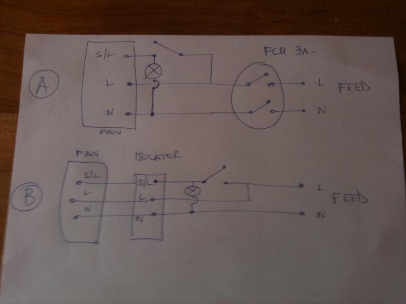
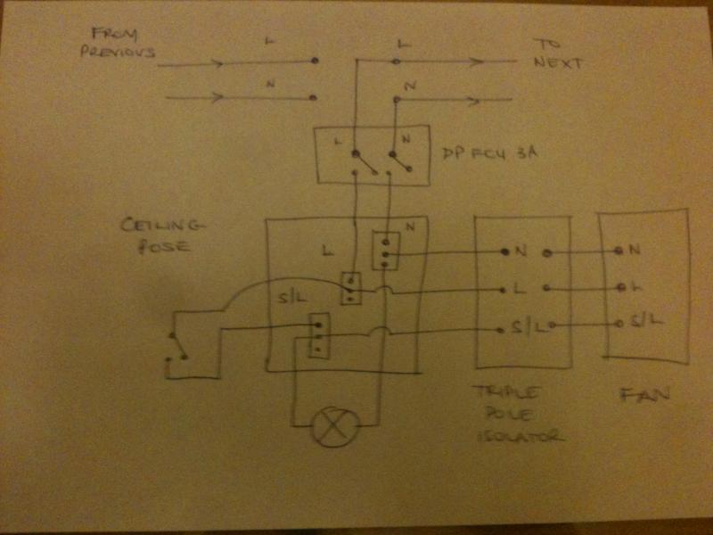
Just trying to plan the ventilation in the kitchen and bathroom in a refurbishment I am doing.
No soffits and property is a top flat, so too costly to go through the roof.
I'd like to use a standard extractor fan and cooker hood to extract out, but the main problem is that the length of ducting I will need is about 9m to get to the outside wall, for both kitchen and bathroom.
Manrose do an in-line centrifugal fan that can cope with 10m of ducting, and is powerful enough to extract enough volume for the rooms (9sq m and 11sq m) to comply with Part F.
http://www.screwfix.com/prods/63459...or-Fans/Manrose-150mm-In-Line-Centrifugal-Fan
I am thinking about running ducting from the bathroom and kitchen and Y join to the in-line fan, and then run the majority of the rest of the run (8m) to the outside wall.
This would have the effect of ventilating both bathroom and kitchen whenever the fan is on (which I guess is ok).
I was thinking about having two switches in parallel (not linked to one another) operating the fan, using standard switches (the bathroom one sited outside the bathroom)
I know this is not a standard way to extract from these rooms, but my long length of ducting is limiting my options.
Problem is I have never use one of these fans before, so if anyone has any experience of using them, or has any ideas about my proposed set up, I'd appreciate it.
Do I also assume that I can forget about zones if I site the in-line fan in the attic void not directly above the bathroom?


