Incorrectly wired lightswitch?

Joined
3 Oct 2012
Messages
5
Reaction score
0
Location
Berkshire
Country
United Kingdom
Hi,

My double gang light switch went 'pop' last week and I have bought a new replacement, But when I opened the old switch to disconnect and wire in the new one, I was confused and concerned by what I saw. So I looked on this forum for wiring diagrams and now I am even more concerned because it appears my existuing lightswitch (which has actually worked fine for years) is in fact incorrectly wired. Can anyone advise?...

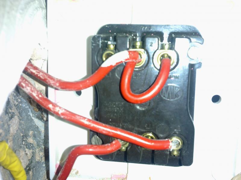
Its a double gang two-way switch, but is only being used as single-way, switching two sets of lights.

The Common of one switch (for clarity, I'll call that Switch A) is actually looped by a small wire to the L2 of the other switch (switch B), which is also fed by a red cable, into L2.
The there are two other red cables connected to each of the L1 and L2 of switch A.

So, Switch A appears to be using all 3 connections, with common looped to Switch B L2. And switch B L1 is vacant.

Oh, and there is a black cable running behind the switch, not conected to anything (appears to have been joined, but not sure).

My new replacement switch has connections labelled 1, 2, 3 for each of the two switches. I have no idea what from the old to connect to what on the new!

Can anyone help?

Thanks
 
Sponsored Links
Do you have anything at the common terminal of "switch B" ?

It sounds like you have a live supply feed coming in at the L2 position of "B" which is linked to the common of "A" then a two way function at "A" the black cores are a looped in neutrals.
Photos by any chance?
 
Connect the new switch exactly as the old one was, including transfering the small link wire from the old switch to the new one. Leave the black wires as they are.

Old switch - New switch

Com - 1
L1 - 2
L2 - 3


Number each wire with a fine marker pen, and then take an in focus close up photograph of the connections before you disconnect any wires from the old switch. That way if you get confused or whatever, you'll have a good reference for us to help you sort it out!
 
Hi,

No nothing on Common of Switch B. Photos to follow in 5 minutes - just need to upload them.

Many thanks for your interest. :)
 
Sponsored Links
The Common of one switch (for clarity, I'll call that Switch A) is actually looped by a small wire to the L2 of the other switch (switch B), which is also fed by a red cable, into L2.

That's fine. The red wire will be your live feed to both switches. The fact that it goes to L2 on switch B instead of COM is not a problem. The switch will work perfectly well like that. :) :) :)

The there are two other red cables connected to each of the L1 and L2 of switch A.

Which suggests that it's been part of a two-way switch setup in the past. Since it's only used as a single now, one of those two red wires will be switched live to a light. So far so good but, if it was mine, I would really, really want to know where the other one went. :confused: :confused: :confused:

You don't mention any wire in switch B COM. They must be (or must have been) or else that switch wouldn't have done anything. have a look at the black wire you mention. Could it have fallen out? :?: :?: :?:

Switch terminals labelled 1,2 and 3 aren't very helpful. Are there any other markings?

Edit: RF Lighting has just answered the 123 puzzle. :) :) :)
 
I will have a guess that at some time it was used for two way switching and it used a now discontinued method using two wire cable between the switches.

With the now discontinued method with the light switches in some combinations it could cause radio interference which was why it was discontinued and also where the lighting was split into two circuits could also produce a borrowed neutral situation.

Likely 1 = Com, 2 = L1 and 3 = L2 but as an electrician I would test with a meter to be sure I don't rely on marking.

This diagram shows one example of each type of light.
lights.bmp

If you look at the two way diagram for X2 you will see the brown line wire goes to both switches. What I guess is that instead of having three cores you only have two and the line is borrowed from the other switch.

If both L1 and L2 are used it's two way lighting. On/off only uses either l1 or L2 not both. Com is always used.
 
Aha. So by connecting the bridged wire to both 1's on new switch, I'm effectively re-wiring differently (to before), but correctly (now making both switches operate the same, instead of one being wired the reverse of the other?)?..
 
In your pic, connect the top wire and the link wire to the two "1" terminals on the new switch.

Connect each of the bottom two wires to the "2" terminals. One wire in each terminal.

That's it.
 
Sometimes you'll get lucky and get the nice helpful people like you have today. Other times, well, just ignore them :LOL:
 
Hi,

No nothing on Common of Switch B. Photos to follow in 5 minutes - just need to upload them.

Many thanks for your interest. :)
The picture actually shows the wiring for two switches you have to look at the connection drawing a diagonal line across the switch

.L1(A)..... L2 (A)... ./.. . COM (B)
(...Switch A.........)/(....Switch B....)
......... COM(A)...../ .... L1(A)... L2(A)
and do as RFL has instructed
 

DIYnot Local

Staff member

If you need to find a tradesperson to get your job done, please try our local search below, or if you are doing it yourself you can find suppliers local to you.

Select the supplier or trade you require, enter your location to begin your search.


Are you a trade or supplier? You can create your listing free at DIYnot Local

 
Sponsored Links
Back
Top