
You are using an out of date browser. It may not display this or other websites correctly.
You should upgrade or use an alternative browser.
You should upgrade or use an alternative browser.
Install a Nest Thermostat - S-Plan - Help :-)
- Thread starter Jord
- Start date
You want to find the cable containing the Red and Yellow wires that go to the old room thermostat.
The Yellow wire should, by some means be connected to the Brown wire of the heating motorised valve. You may have to trace it from one junction box to the other to find an intermediate connection. [The back wire maybe?]
With the heating wiring isolated, once you find the Yellow wire, note which terminal it is in and disconnect it [be careful not to disturb any other wires in the same terminal they stay as they are]. Then do the same with the Red wire from the same cable.
At this point I would normally test with a multimer to be sure I have the right wires. With the multimeter set to resistance connected to the Red and Yellow wires, get an assistant to turn the thermostat up to max. The resistance measured should be very low. When the thermostat is turned to minimum the resistance is very high. If so, you have the right wires.
Having noted where the Red and Yellow wires have just been removed from, a link is inserted to join the two terminals that they have just been taken out of together to complete the circuit.
The rest of the wires in the thermostat cable [Blue & Earth] can now be removed and the whole cable extracted from the junction box. You may now do whatever you wish with it.")
The Yellow wire should, by some means be connected to the Brown wire of the heating motorised valve. You may have to trace it from one junction box to the other to find an intermediate connection. [The back wire maybe?]
With the heating wiring isolated, once you find the Yellow wire, note which terminal it is in and disconnect it [be careful not to disturb any other wires in the same terminal they stay as they are]. Then do the same with the Red wire from the same cable.
At this point I would normally test with a multimer to be sure I have the right wires. With the multimeter set to resistance connected to the Red and Yellow wires, get an assistant to turn the thermostat up to max. The resistance measured should be very low. When the thermostat is turned to minimum the resistance is very high. If so, you have the right wires.
Having noted where the Red and Yellow wires have just been removed from, a link is inserted to join the two terminals that they have just been taken out of together to complete the circuit.
The rest of the wires in the thermostat cable [Blue & Earth] can now be removed and the whole cable extracted from the junction box. You may now do whatever you wish with it.
Last edited:
Not exactly sure what you mean, but if you mean how would I suggest you get power to it I've used various methods depending on the location of the components and the construction and layout of the property.
If possible my personal preference is always to wire the Heat link to the Thermostat. I have drilled holes in and threaded wires behind plasterboard, on occasion I have run a new wire in the room behind especially if it's a cupboard or a cloakroom [in my hallway at home, there's an understairs cupboard behind where my thermostat is located] and drilled though to the side where the thermostat is to be located. Once I ran some mini trunking at the side of a door frame and put the cable in that. On another occasion I lifted the wallpaper cut a groove with a knife and buried some 12v alarm cable in that and re-stuck the wall paper. I have used the existing thermostat cable and extended the other end from where it used to be connected to the wiring centre to the Heat link. And on a one occasion where it was really tricky, I used a separate Nest supplied 'plug in' power supply.
Not my personal preference, but thin 12v black cable run outside of the house might be a possibility. Between floors it might be able to be hidden behind a drainpipe. However, most homes seem to have a proliferation of TV, internet cables on show outside already, one more may not be an issue.
Hope some of that helps.
just a quick question.
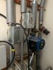
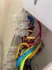
Image 9 this show the valves - i took the left one as the heating valve middle is the HW valves, what is the blue one? just want to check
Image 10 - if this left valve CH is correct above then this is the wire which comes in the central wiring station. The brown wire is the live which i need to trace too?
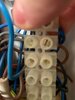
Image 11 - this the point above is correct then this is where the brown wire connect to which is a black one. both the black wire and brown above i believe come from the thermostat (red and yellow cables which have changed colour once travelled through the other wiring station)
If that is all correct then i would in the simple work connect the brown and 2 grey wires together to complete the circuit? Which would mean the red and yellow thermostat cable are free from the circuit ( i would test this too).
Wondering if im on a good path?
Image 9 this show the valves - i took the left one as the heating valve middle is the HW valves, what is the blue one? just want to check
Image 10 - if this left valve CH is correct above then this is the wire which comes in the central wiring station. The brown wire is the live which i need to trace too?
Image 11 - this the point above is correct then this is where the brown wire connect to which is a black one. both the black wire and brown above i believe come from the thermostat (red and yellow cables which have changed colour once travelled through the other wiring station)
If that is all correct then i would in the simple work connect the brown and 2 grey wires together to complete the circuit? Which would mean the red and yellow thermostat cable are free from the circuit ( i would test this too).
Wondering if im on a good path?
Attachments

D
Deleted member 267285
The blue “valve” as you’re calling it is the pump, and that’s activated once either or both zone valve opens.
Can’t see any grey wires, but they’re usually permanent live.
Can’t see any grey wires, but they’re usually permanent live.
Sorry, I don't understand the question, and I don't see any grey wires. Two grey wires would normally be to the motorised valves, and would provide the permanent live for them to control the boiler. But they would be nothing to do with the thermostat wiring.
apologies, so now i am trying to locate where the red and yellow thermostat wires go to.
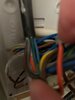
Question 1: Image 8 is the mini wiring centre which looks like the thermostat goes there first before connecting to different wires to go to the main wiring centre.
If this is the case:
Yellow = Black
Red = Brown
Is this correct?
Questions 2: Image 11 (updated) for CH valve Brown wire (1) this connects to the black wire (2) this used to the yellow wire from the thermostat. and above it (4) used to be the red from the thermostat.
What are the grey wires?
Would i connect the grey wires and brown wire (1) to complete the circuit and therefore the thermostat wires have been taken out of the circuit?
hope that makes better sense now?
If thats the case then i can figure a way to connect the two wire taken out of the circuit to the heatlink?
Attachments
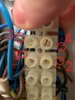
Questions 2: Image 11 (updated) for CH valve Brown wire (1) this connects to the black wire (2) this used to the yellow wire from the thermostat. and above it (4) used to be the red from the thermostat.
That looks a bit more promising. So, as I understand it you are telling us that:
CH MV brown wire.......>black wire.......>Suspected Yellow wire to thermostat.
OK so note where the yellow wire is connected and remove it.
Also note where the red wire in the same cable as the yellow one is connected and remove that.
Now carry out the test I mentioned earlier, if you can't do it I suggest that you get someone who can, just to be sure.
At this point I would normally test with a multimer to be sure I have the right wires. With the multimeter set to resistance connected to the Red and Yellow wires, get an assistant to turn the thermostat up to max. The resistance measured should be very low. When the thermostat is turned to minimum the resistance is very high. If so, you have the right wires.
Once you have determined it is the thermostat cable just insert a link to join the two terminals together that you have just removed the red and yellow wires from.
What are the grey wires?
I mentioned them earlier.
Two grey wires would normally be to the motorised valves, and would provide the permanent live for them to control the boiler. But they would be nothing to do with the thermostat wiring.
No.Would i connect the grey wires and brown wire (1) to complete the circuit and therefore the thermostat wires have been taken out of the circuit?
they would be nothing to do with the thermostat wiring.
thanks for the help as always
So in image 8
'If' this is the thermostat wires i would remove the red and yellow out of the connector and then simple connect the black and brown together in the same connector hole?
This would take the red and yellow wire out so i could then look to connect these to the heatlink and nest thermostat?
Attachments
That all sounds good to me ") . Provided that there are just the black and brown wires that can be seen in the photo left behind once the red and yellow wires are removed. [by that I mean there aren't any other wires we can't see in the far side of the two terminals]
. Provided that there are just the black and brown wires that can be seen in the photo left behind once the red and yellow wires are removed. [by that I mean there aren't any other wires we can't see in the far side of the two terminals]
The blue wire and earth from the same cable can simply be disconnected and removed. The cable should be completely disconnected from any mains wiring before using it for 12v
. Provided that there are just the black and brown wires that can be seen in the photo left behind once the red and yellow wires are removed. [by that I mean there aren't any other wires we can't see in the far side of the two terminals]The blue wire and earth from the same cable can simply be disconnected and removed. The cable should be completely disconnected from any mains wiring before using it for 12v
- Joined
- 11 Apr 2022
- Messages
- 998
- Reaction score
- 218
- Country

Would something like this work to provide 12v dc power to a Nest thermostat with the 240v ac supply coming from the wiring centre.Not exactly sure what you mean, but if you mean how would I suggest you get power to it I've used various methods depending on the location of the components and the construction and layout of the property.
If possible my personal preference is always to wire the Heat link to the Thermostat. I have drilled holes in and threaded wires behind plasterboard, on occasion I have run a new wire in the room behind especially if it's a cupboard or a cloakroom [in my hallway at home, there's an understairs cupboard behind where my thermostat is located] and drilled though to the side where the thermostat is to be located. Once I ran some mini trunking at the side of a door frame and put the cable in that. On another occasion I lifted the wallpaper cut a groove with a knife and buried some 12v alarm cable in that and re-stuck the wall paper. I have used the existing thermostat cable and extended the other end from where it used to be connected to the wiring centre to the Heat link. And on a one occasion where it was really tricky, I used a separate Nest supplied 'plug in' power supply.
Not my personal preference, but thin 12v black cable run outside of the house might be a possibility. Between floors it might be able to be hidden behind a drainpipe. However, most homes seem to have a proliferation of TV, internet cables on show outside already, one more may not be an issue.
Hope some of that helps.
RS PRO AC-DC Constant Voltage LED Driver 6W 12V | RS Components
DIYnot Local
Staff member
If you need to find a tradesperson to get your job done, please try our local search below, or if you are doing it yourself you can find suppliers local to you.
Select the supplier or trade you require, enter your location to begin your search.
Please select a service and enter a location to continue...
Are you a trade or supplier? You can create your listing free at DIYnot Local
Similar threads
- Replies
- 6
- Views
- 10K
- Replies
- 6
- Views
- 12K
- Replies
- 14
- Views
- 5K