install wireless room stat to this system

Joined
6 Dec 2009
Messages
21
Reaction score
0
Location
Cardiff
Country
United Kingdom
Hi
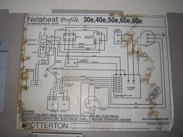
Recently moved into new house which has standard boiler (potterton hetaheat) for hot water / heat.
There is no room stat and I'd like to have one. This would need to be wireless (pref honeywell CM927) - would then leave heating control to permanently on and control heating via stat.
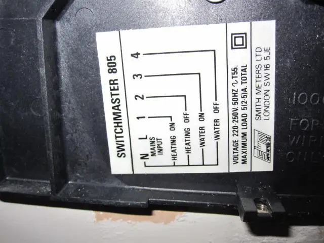
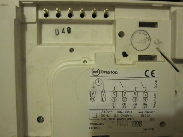
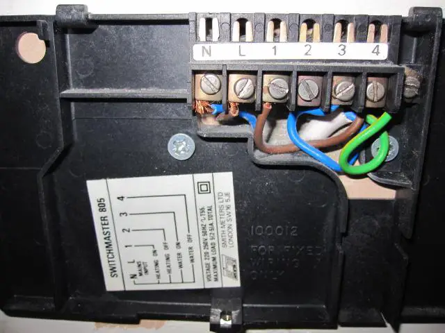
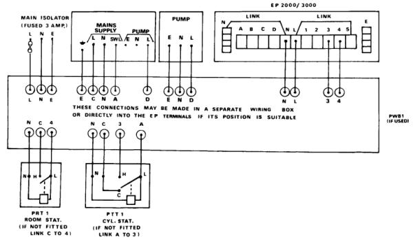
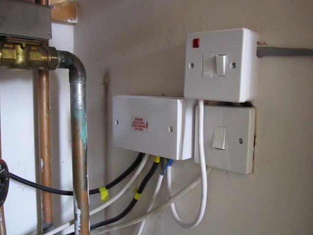
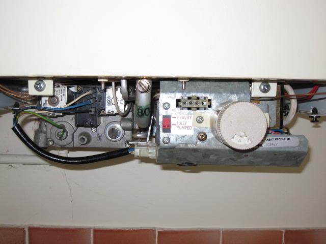
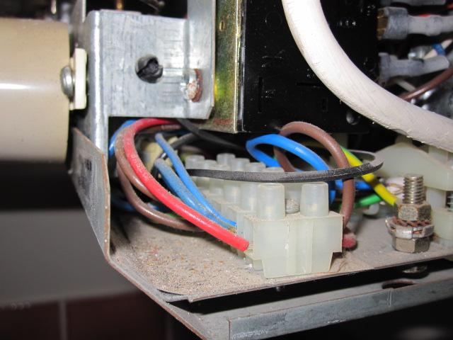
How would I install it? I've posted some pics of the system as it is at the moment - the wiring control box looks like a jumble and I'm not sure if wiring directly to the boiler would be an option. There is a mains feed in the airing cupboard for the reciever, but where would I wire the control to?
All suggestions gratefully recieved. - PHOTOS BELOW
 
Sponsored Links
the cm927 would need to control the central heating 2 port zone valve, this is how I would do it...

permanent live and neutral to reciever

ch output from programmer to A on receiver

brown wire from 2 port to B on receiver

there are other ways to do it but looking at your wiring this is perhaps the most straight forward way of doing it.
 
I think it will be easiest to rewire from fresh, rather than try to sort out the jumble in the junction box. ;)

I see you have two motorized valves (the blue and silver boxes on the pipe at the top of the second pic down), so you have what is known as an "S Plan" system. One valve controls flow through the HW cylinder, the other through the radiators.

View media item 71
You need to buy a "wiring centre". There are two types: the easiest to use just contains a strip connector with 10 or 12 pairs of connections.

This is the basic wiring diagram, but there are some mods for your system, which I will give below.

View media item 72
1. Pump
The pump has to be wired directly to the boiler. Connect it to Terminal 9 and run a wire from terminal 9 to the "Pump Live" terminal on the boiler. The Pump's Neutral and Earth connections are made in the wiring centre.

2. Power supply
The boiler and wiring centre both need a permanent supply (from a fused outlet or spur), so it is not as shown in the diagram. You can either provide the main connection to the boiler and then run three wires from there to the wiring centre terminals 1-3, or you can do it the other way round. What you should not do is supply the boiler and wiring centre from different fused outlets - it could be dangerous. Which you do will depend on the current arrangement.

3. Hot water The existing programmer can retained for HW timing. Just connect up the HW ON terminal as show. The CH ON terminal is not used, so the CH side of the existing timer is disabled.

4. CM927. This connects in place of the room stat shown. Wiring is as follows:

Connect L to Terminal 1
Connect N to Terminal 2
Connect A to Terminal 4
Connect B to Terminal 5

Link Terminal 1 to Terminal 4

Switched live. This connects from terminal 10 to SwL on the boiler.

The cable from the wiring centre should have four wires plus the earth wire. They are used for: Live, Neutral, Pump Live, Switched Live and Earth.

Come back if you need any clarification.
 
Sponsored Links
Thanks both
Is the 1st option suggested by picasso any less valid than the rewire option. Will it work just as well, I'm sure if I try rewiring it all something will be missed / wrongly wired?
grateful for all your help
 
Option #3 ;)

Fit the receiver beside your existing timeclock.
Take a pic of the connections behind the timer and I'll tell you exactly which wire goes where :)
 
Option #3 ;)

Fit the receiver beside your existing timeclock.
Take a pic of the connections behind the timer and I'll tell you exactly which wire goes where :)

Best option IMO, unless your comfortable with heating controls a re-wire isn't really needed, a tidy up of the existing could be easily done with a bit of patience.
 
Best option IMO, unless your comfortable with heating controls a re-wire isn't really needed, a tidy up of the existing could be easily done with a bit of patience.
I wasn't suggesting a complete rewire, just a tidy up, replacing the existing mishmash of choc-blocks in a box with a wiring centre. The only new cable suggested was the one to the boiler and this is optional - the existing wires could be used.
 
Remove brown from terminal one, extend it to reach 'B' in the Cm927 (use connector block).

Connect terminal 1 of the timer to 'A' of your CM927.

Take a live, neutral and earth from the timer ;)

5 Core cable is the best for this, butt the cm927 receiver up close to the timer so you cant see any cable showing ;)

Basically the power comes from to the timer (L), to the roomstat and back down that brown wire in terminal one.

Let me know if you have any problems.
 

DIYnot Local

Staff member

If you need to find a tradesperson to get your job done, please try our local search below, or if you are doing it yourself you can find suppliers local to you.

Select the supplier or trade you require, enter your location to begin your search.


Are you a trade or supplier? You can create your listing free at DIYnot Local

 
Sponsored Links
Back
Top