Hi All,
I'm looking to replace my existing thermostat (Worcester Bosch MT10RF-Mechanical RF thermostat) with a nest 3rd gen and wondered if you could offer some advice on the wiring of it?
1. I'd like to disable the existing receiver from the boiler which I plan to do, by removing the ribbon cable from the connection shown below, is that ok?

The connections for the nest heat link are shown below:

My current boiler connections are shown below:

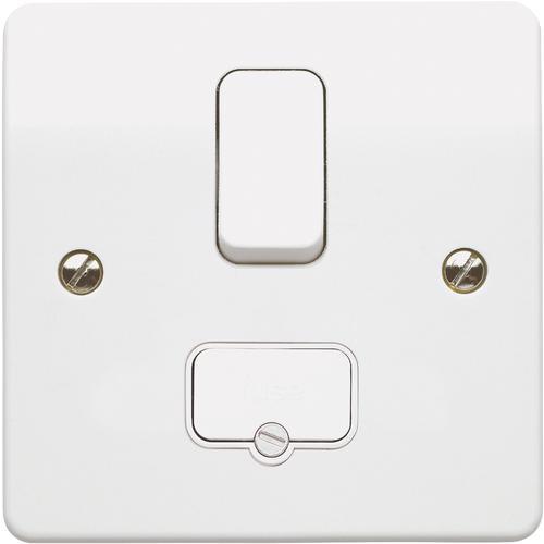
Currently a L,N and E comes from an FCU underneath the boiler and connects to the white terminal block (labelled 230 V IN LNE) on the right hand side of the picture above.
2. Am I right in thinking I should take the connections that terminate into the FCU and place these into the L,N and E connections in the heat link (leaving the connections where they are in the white terminal block) and then install a new cable from the FCU and connect it to the same terminals in the heat link?
3. For the heating connections in the heat link (terminals 2 + 3). Connect terminal 2 (common) to the live in the heat link. Connect terminal 3 (heat link) to the yellow terminal block (boiler control connection), terminal CH, remove the link between the orange terminal block, terminal L and the yellow terminal block, terminal CH.
4. Now, for the hot water connections. Can I leave as they are, or do these have to be connected to the heat link as well? If so, terminals 5 + 6 (in the heat link). Connect terminal 5 (common) to the live in the heat link. Connect terminal 6 (heat link) to the yellow terminal block (boiler control connection), terminal HW, remove the link between the orange terminal block, terminal L and the yellow terminal block, terminal HW. The reason I ask is on the Worcester Bosch wiring diagram it shows a connection for the pre-heat to be made in the programmer, but I can't see any reference to this with the nest.
Worcester Bosch wiring diagrams:

Cheers
I'm looking to replace my existing thermostat (Worcester Bosch MT10RF-Mechanical RF thermostat) with a nest 3rd gen and wondered if you could offer some advice on the wiring of it?
1. I'd like to disable the existing receiver from the boiler which I plan to do, by removing the ribbon cable from the connection shown below, is that ok?

The connections for the nest heat link are shown below:

My current boiler connections are shown below:

Currently a L,N and E comes from an FCU underneath the boiler and connects to the white terminal block (labelled 230 V IN LNE) on the right hand side of the picture above.
2. Am I right in thinking I should take the connections that terminate into the FCU and place these into the L,N and E connections in the heat link (leaving the connections where they are in the white terminal block) and then install a new cable from the FCU and connect it to the same terminals in the heat link?
3. For the heating connections in the heat link (terminals 2 + 3). Connect terminal 2 (common) to the live in the heat link. Connect terminal 3 (heat link) to the yellow terminal block (boiler control connection), terminal CH, remove the link between the orange terminal block, terminal L and the yellow terminal block, terminal CH.
4. Now, for the hot water connections. Can I leave as they are, or do these have to be connected to the heat link as well? If so, terminals 5 + 6 (in the heat link). Connect terminal 5 (common) to the live in the heat link. Connect terminal 6 (heat link) to the yellow terminal block (boiler control connection), terminal HW, remove the link between the orange terminal block, terminal L and the yellow terminal block, terminal HW. The reason I ask is on the Worcester Bosch wiring diagram it shows a connection for the pre-heat to be made in the programmer, but I can't see any reference to this with the nest.
Worcester Bosch wiring diagrams:

Cheers


