Light and extractor fan won’t run together when operated by new kinetic switch?

Joined
24 Aug 2023
Messages
8
Reaction score
0
Country
United Kingdom
This is quite an obscure question and was hoping that someone could help me out.

Currently have a bathroom running a light & extractor fan that operates off a horrid pull cord switch. I was hoping to change that to a wireless kinetic switch system I found off Amazon, essentially a Quinetic light switch.

Bathroom light & fan both come on when you pull the cord. Light goes out when you pull the cord again and fan goes off on (presumably) a timer after 1-2 mins or so.

I’ve wired it up so that the wireless switch operates the light but it’s a bit odd. The pull cord still operates the fan and the wireless switch has no effect on the fan.

For example the pull cord has to be in the ‘on’ position for the wireless receiver to get power. Wireless switch operates the light perfectly and turns on extractor fan. However the fan never, ever goes out unless you pull the cord again and I was hoping to do away with the whole pull cord system. How do I run this so that the fan goes off as normal after 1-2 mins after turning the wireless switch off?

In the instructions the receiver goes in the light and not at the switch.

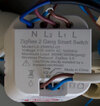
Below are pics of the wireless setup:

IMG_5263.jpeg


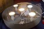
Below is the original pendant before the receiver:

IMG_5258.jpeg
 
Sponsored Links
The new module is connected directly to the light so there's no way its going to affect the fan! The instructions are obviously only a guide and dont cover the situation you have.

You need to install that module in place of the switch, so that its output connects to the light and the fan, put the light back to how it was.
 
You shouldn't have removed the light wires from the rose - merely wired the new switch with the old switch wires - plus permanent live and neutral if required.
 
  • Thanks
Reactions: CBW
Sponsored Links
It could be the picture, but do you have 2 wires (black and blue) going to the 1 Wago style connector? Can you post a photo of the wiring configuration on that switch, and possibly the ones in the instructions?
 
Thank you all. Here are clearer photos of the original pendant and of the pull switch.

Not sure why there’s a red sleeve on neutral on the pull cord.

IMG_5308.jpeg


IMG_5309.jpeg


It could be the picture, but do you have 2 wires (black and blue) going to the 1 Wago style connector? Can you post a photo of the wiring configuration on that switch, and possibly the ones in the instructions?
I believe there was three cables, two black one blue going into one connector. Was quite a struggle fitting them in. No new pictures sorry as I already put the old pendant back up.

IMG_5310.jpeg


Also, if I wire up the receiver instead of the switch what do I do with the earth cable? Use a connector block?
Would I simply wire up one Wago and leave the other empty? Would it be the in or out? Thanks for your patience
 
Last edited:
This is all you needed to do:

1692991659335.png


If you want to remove the pull switch then disconnect, at the rose, the Black with the red sleeve and the red that comes from the same cable and, of course its earth wire.
 
This is all you needed to do:

View attachment 312150

If you want to remove the pull switch then disconnect, at the rose, the Black with the red sleeve and the red that comes from the same cable and, of course its earth wire.
Many thanks for the diagram EFL. I’ve tried it this way and it doesn’t seem to work, no power to the receiver or anything, no sign of life. I’ve also tried with the other red for Live in.

Also not sure what I did wrong or if it’s related but the under-cabinet hardwired LED lights in the kitchen have strangely broken during this. One baton stopped entirely and another baton now flashes at a regular pace. Perhaps cutting it at the breaker switch destroyed it? I can’t imagine how this could be connected to the bathroom wiring attempt?

Anyway, here is a photo of the wiring after copying your diagram:

IMG_5539.jpeg
 
The yellow wire seems likely the trigger wire for the fan, the problem is room, I have used a relay DSC_6061r.jpg but the light was rather large, DSC_6056.jpg with loads of room to fit the relay, even so in hind sight, I made a mistake as once the chandelier was fitted, to get access is not easy. 20220529_211956.jpg and in hind sight, would have been better mounted in a adaptable box in the loft. I have not looked at the kinetic relay, I have looked at my software and there does not seem to be an option to turn off one contact so many minutes are the other contact, so you will need to use the built in timer. Seem to remember should be 15 minutes run on.

But the first question has to be were your going to fit those large connector blocks.
 
The yellow wire seems likely the trigger wire for the fan

But the first question has to be were your going to fit those large connector blocks.

Have tried the yellow wire instead of the black with red sleeve. Light seems to turn on and off at the pull cord but still nothing to the receiver, also the fan didn’t turn on and off once I did that.

Receiver will go in a hollow space in the ceiling. Will be a nuisance but I can make it work.
 
Those Neutrals look like they’re not in fully, and it does look different from @EFLImpudence ‘s diagram, can’t work out whether you have N connected? Any test gear?
 
Many thanks for the diagram EFL. I’ve tried it this way and it doesn’t seem to work, no power to the receiver or anything, no sign of life. I’ve also tried with the other red for Live in.

Also not sure what I did wrong or if it’s related but the under-cabinet hardwired LED lights in the kitchen have strangely broken during this. One baton stopped entirely and another baton now flashes at a regular pace. Perhaps cutting it at the breaker switch destroyed it? I can’t imagine how this could be connected to the bathroom wiring attempt?

Anyway, here is a photo of the wiring after copying your diagram:

View attachment 312590
I really don't know how you think that:
1693432799880.png

is the same as this
1693432599247.png


Restore the 2 wires arrowed green, disconnect the 2 wires arrowed red:
1693432564066.png

Then add the brown, black and grey that EFL showed.
 
I’ve tried it this way and it doesn’t seem to work, n
You have not followed the diagram.
You need to ADD wires from the rose to the switch device so all of the neutrals are connected together all of the lines are connected, all of the switched lines are connected.

You have removed some wires from the terminals and connected them to the switch device, which means that they are no longer connected to the others.
 

DIYnot Local

Staff member

If you need to find a tradesperson to get your job done, please try our local search below, or if you are doing it yourself you can find suppliers local to you.

Select the supplier or trade you require, enter your location to begin your search.


Are you a trade or supplier? You can create your listing free at DIYnot Local

 
Sponsored Links
Back
Top