"Loop" Connector.

Joined
20 Feb 2017
Messages
935
Reaction score
140
Location
Melbourne, Australia
Country
Australia
I draw your attention to a query relating to the wiring of a UK Light Switch.
This query has been posted on the North American site of https://www.diychatroom.com/f18/wiring-light-switch-issues-638161/

The photos show that a SPST switch, which appears to incorporate a "Loop" connection for the Neutrals, is to be replaced with a SPDT switch - without a "Loop" connection.

It can be seen that the paired Brown wires should be connected to the "COM" terminal of the new switch and the single Brown wire should be connected to L1 of the new switch.

The question remains, what insulated connector would/should be used in the UK for the Neutral "Loop" connector.

(Obviously, it would NOT be a "Wire Nut" - as used in North America.)

Now-a-days, it could be a Wago 222 connecter - but what would have been used before these existed and could be used today?

In Australia, the ubiquitous "BP" connector is used for such purposes. (See https://commons.wikimedia.org/wiki/File:Australian_Set_Screw_Connectors.jpg
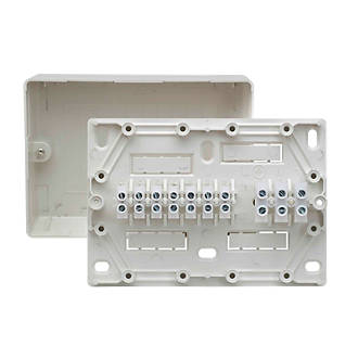
and https://commons.wikimedia.org/wiki/File:Australian_Internal_Surface_Mounted_Junction_Box.jpg)

I ask this as "a question of interest" and I would not attempt to advise the OP (Chunter28), whom I did advise to re-post on this site, without much greater knowledge of wiring requirements in the UK than the little which I have gleaned from this site.
 
Sponsored Links
but what would have been used before these existed

Just an individual one of these...

CBBR1059-40.jpg


could be used today?

Yes, perfectly fine to use.
 
Just an individual one of these...

CBBR1059-40.jpg


Yes, perfectly fine to use.
Thank you and I did think that that was the case!

My understand is that these "Terminal Connector Blocks" are commonly called "Choc Blocks", because of their size and (previously) the plastic used was "chocolate" coloured.
 
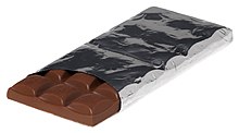
my understanding is that it's because a block of them somewhat resembles a bar of chocolate

 
Sponsored Links
My understand is that these "Terminal Connector Blocks" are commonly called "Choc Blocks", because of their size and (previously) the plastic used was "chocolate" coloured.
Indeed. I'm not so sure about the colour (they seem to have been most commonly white or translucent 'clear' for a very long time - and I don'r recall having seen than many brown ones for a very long time), but 2- or 3-terminal bits of such connector strips certainly resemble to some extent the shape/size of 'bits' broken off a bar of chocolate. They are known by a whole host of names.

Kind Regards, John
 
In many countries the loop is in the switch box, however this means there is no permanent line at the ceiling rose so hard to fit emergency lights or cooling fans, it also means more cable is used, and our method of wiring was developed at the end of world war two when copper wire was in short supply, which is likely why we do the loop at the ceiling rose.

Doing the loop at the switch started with the introduction of MR16 lamps which often had no provision for the loop, using a lighting junction box would be the best option, but these seemed to arrive on the market after the MR16 fitting and by that time where original equipment electricians has moved to using the switch box for the loop, it also has some advantages today where European import light switches to do special functions require a neutral.

It has been common for years to use block connectors for the common wire with multi-switch systems where an intermediate switch is used, why the intermediate switches don't have a terminal for the common wire I don't know, it would make sense.

We also see back boxes with strips of block connector used with central heating systems where the installer is too tight to use a proper box.
 
We also see back boxes with strips of block connector used with central heating systems where the installer is too tight to use a proper box.
That is exactly what 'proper boxes' used to be, I removed one this week.
 
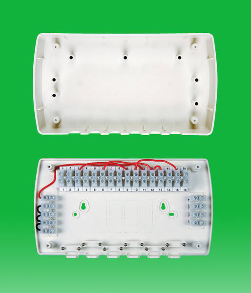
These
SMTRT049A.JPG
are numbered and pre-linked to follow Honeywell plan, and have cable clamps, with the socket back box and blanking plate there were often no clamps and chock block was left floating with each installer developing his own unique plan so maintenance was difficult. OK some boxes were not as good
ae235
but even that one the terminals are fixed and it does have the 10 terminals to match honeywell plan. Ups I see yes problem with first one, that one could not follow Honeywell plan as too many terminals.

Yep, and I think I posted something similar a few months back where the clamps had not been used. But the original wiring centres were nothing more than a back box, strip of choc block and a blanking plate with some sort of name on it, either printed/transfer or stuck on. Eventually some came up with an arrangement to fix the connectors in place.

I replaced a Honeywell one last week for a boiler replacement.
 
Last edited:

DIYnot Local

Staff member

If you need to find a tradesperson to get your job done, please try our local search below, or if you are doing it yourself you can find suppliers local to you.

Select the supplier or trade you require, enter your location to begin your search.


Are you a trade or supplier? You can create your listing free at DIYnot Local

 
Sponsored Links
Back
Top