Ah, anything in the garage is just what I have inherited - I haven't touched any of that!

You are using an out of date browser. It may not display this or other websites correctly.
You should upgrade or use an alternative browser.
You should upgrade or use an alternative browser.
Lost neutral, or something else?
- Thread starter GeoffTitch
- Start date
Right, managed to fix that little issue (the original wiring had a crossed wire, God only knows how it worked before!) but we seem to have at least one dead wire in the original SWA, and it currently terminates in the shower room anyway which seems a pretty daft place for it to finish up, so....
Was thinking of getting a spark in to replace the cable and take the opportunity to sort out some of the wiring mess (well, I am going to do the digging of the trench, and pull the cables through - labour intensive thus expensive but non-technical manual bits - and he will come do the 'connect it together, check it out and sign it off' part), then get him to install a CU in the [dry] pump room and take the SWA to there.
However (as I like to know what I am looking at)...
At the moment the mains feed comes from the meter into a Henley where it splits into 3 (main house CU, smaller fusebox used for poolhouse, which is what I am about to have replaced, and third feed up to Solar PV system - see photo earlier). Is it normal to split the mains feed like that? The PV seems to be on 16mm tails, whereas the other two are on... 'chunkier'... cables.
Reason I am asking is I was thinking of getting the sparks to set it up as follows:
Mains feed to split (again?! Can he do 4 feeds off the mains via one block?) into:
a) 2 way CU (63A RCD) in garage (where existing old fuse box is) to swimming pool filter pump (32A) and socket (16A) - it needs to be this end, as it goes to a timer which drives the heating pump in the room next door). From there it will feed into the 2 cores of a 10mm SWA to take the power to the pump room itself, where it connects directly to th pump via an isolator - most of this is existing, it's just the 'connection to mains' that needs to change. I understand that both the CU and the SWA will be earthed to the earth block that is already in place. No idea where it goes from there to earth (checking for PME was mentioned) - that's for the spark to sort out")
b) Take mains directly down the other 2 of the 4 cores in a new 10mm2 SWA to a new (100A RCD) CU in the pump room itself, where it will then feed the 4 separate circuits already in place: lights (6A), sockets (16A), sauna (40A) and shower (7.5kw on 40A). I think that end is then going to earth out to an earth rod - local TT at the pump room end to earth off both the CU and the SWA - we are only about a metre above the water table here.
Is it ok for him to feed mains directly into 2 cores of the SWA (it will connect to the CU/100A RCD at the other end) or should he be telling me it needs to go through some sort of isolator at the head end? before it goes into the SWA? (He seemed to leave that out, but kept going on about wiring the house, but I would have thought that was sensible? Or is that overkill? - no pun intended!)
Obviously I realise it needs a qualified Part P sparks to do this - no new circuits but it is replacing an existing circuit and, in part, is (re)wiring a shower. In any event, I'd want to know it is safe.
But I also want to understand what is going on and make sure he is not telling me stuff I don't need (as the last one I got in to quote started with "we need to change the incoming RCD, the whole mains CU and rewire the whole house"...)!
He seemed to be talking about daisy chaining the existing Henley into yet another Henley (?) to split the supply where it can feed the small CU and go 2 of the 4 core SWA to feed the other larger CU at the other end - these are two separate circuits, not one a sub off the other. Couldn't he just take a 4th feed directly off the existing Henley?
He was also talking about bonding the earth to the water mains (the comment was associated with 'oh, that can be expensive, needs a thick cable mate, it's not pretty') and exporting it to the poolhouse - Wouldn't the TT system in the poolhouse be sufficient for those circuits (subject to testing, of course!)
Was thinking of getting a spark in to replace the cable and take the opportunity to sort out some of the wiring mess (well, I am going to do the digging of the trench, and pull the cables through - labour intensive thus expensive but non-technical manual bits - and he will come do the 'connect it together, check it out and sign it off' part), then get him to install a CU in the [dry] pump room and take the SWA to there.
However (as I like to know what I am looking at)...
At the moment the mains feed comes from the meter into a Henley where it splits into 3 (main house CU, smaller fusebox used for poolhouse, which is what I am about to have replaced, and third feed up to Solar PV system - see photo earlier). Is it normal to split the mains feed like that? The PV seems to be on 16mm tails, whereas the other two are on... 'chunkier'... cables.
Reason I am asking is I was thinking of getting the sparks to set it up as follows:
Mains feed to split (again?! Can he do 4 feeds off the mains via one block?) into:
a) 2 way CU (63A RCD) in garage (where existing old fuse box is) to swimming pool filter pump (32A) and socket (16A) - it needs to be this end, as it goes to a timer which drives the heating pump in the room next door). From there it will feed into the 2 cores of a 10mm SWA to take the power to the pump room itself, where it connects directly to th pump via an isolator - most of this is existing, it's just the 'connection to mains' that needs to change. I understand that both the CU and the SWA will be earthed to the earth block that is already in place. No idea where it goes from there to earth (checking for PME was mentioned) - that's for the spark to sort out
b) Take mains directly down the other 2 of the 4 cores in a new 10mm2 SWA to a new (100A RCD) CU in the pump room itself, where it will then feed the 4 separate circuits already in place: lights (6A), sockets (16A), sauna (40A) and shower (7.5kw on 40A). I think that end is then going to earth out to an earth rod - local TT at the pump room end to earth off both the CU and the SWA - we are only about a metre above the water table here.
Is it ok for him to feed mains directly into 2 cores of the SWA (it will connect to the CU/100A RCD at the other end) or should he be telling me it needs to go through some sort of isolator at the head end? before it goes into the SWA? (He seemed to leave that out, but kept going on about wiring the house, but I would have thought that was sensible? Or is that overkill? - no pun intended!)
Obviously I realise it needs a qualified Part P sparks to do this - no new circuits but it is replacing an existing circuit and, in part, is (re)wiring a shower. In any event, I'd want to know it is safe.
But I also want to understand what is going on and make sure he is not telling me stuff I don't need (as the last one I got in to quote started with "we need to change the incoming RCD, the whole mains CU and rewire the whole house"...)!
He seemed to be talking about daisy chaining the existing Henley into yet another Henley (?) to split the supply where it can feed the small CU and go 2 of the 4 core SWA to feed the other larger CU at the other end - these are two separate circuits, not one a sub off the other. Couldn't he just take a 4th feed directly off the existing Henley?
He was also talking about bonding the earth to the water mains (the comment was associated with 'oh, that can be expensive, needs a thick cable mate, it's not pretty') and exporting it to the poolhouse - Wouldn't the TT system in the poolhouse be sufficient for those circuits (subject to testing, of course!)
- Joined
- 27 Jan 2008
- Messages
- 28,917
- Reaction score
- 3,538
- Location
- Llanfair Caereinion, Nr Welshpool
- Country

I have not seen one RCD in the picture and it is clearly very old. The
 I am assuming one of those wires (bottom or right) goes to a switch?
I would guess since wired there have been many changes including how the water and gas get to the property and it is likely it also has some old ELCB-v fitted so one has to be careful bonding as it could make things worse not better.
When I came to do an upgrade once the owner was very good with his question he said I know it all needs doing but can't afford to do it all now so assuming to be done over 5 years what would you recommend I get done each year.
So I split the work into 5 doing of course most dangerous bits first. This is common when taking over an old set of buildings. It may mean some temporary work which will latter be removed and over all may increase the cost but that way you get the electrician to prioritise what needs doing first.
I have in the past fitted for example a 100 mA RCD which I know once complete will have no purpose. But was needed so I could bond with a TT supply which had originally a ELCB-v fitted.
I have also had a budget per month and this again is not unusual. For me it was not what I wanted but even the HSE accepts remedial work takes time. Factories are rarely closed they are given X months to comply.
So talk to your electrician and work out a plan with him.
I have not seen one RCD in the picture and it is clearly very old.
1974. Currently no RCDs anywhere. The intention is to introduce two RCD protected circuits for this outbuilding only, at this stage.
I am assuming one of those wires (bottom or right) goes to a switch?
Yes, that's just part of the existing lighting circuit within the outbuilding. I just took the cover off to check the wiring. 'In, out, lamp switch'
I would guess since wired there have been many changes including how the water and gas get to the property and it is likely it also has some old ELCB-v fitted so one has to be careful bonding as it could make things worse not better.
No gas anywhere in the village. No changes to incoming water feed since 1974. House was my fathers from new build.
When I came to do an upgrade once the owner was very good with his question he said I know it all needs doing but can't afford to do it all now so assuming to be done over 5 years what would you recommend I get done each year. So I split the work into 5 doing of course most dangerous bits first.
Ditto, I am aware that the main house CU could do with replacing, but not now. However this outbuilding part does need finishing.
So talk to your electrician and work out a plan with him.
Will do, just wasn't entirely happy/confident with what was being said.
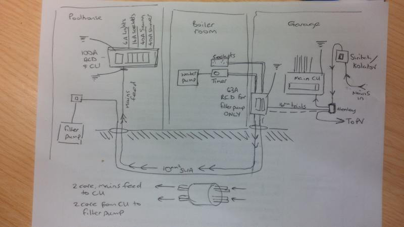
Ok, this should be the rough layout of what I am proposing the electrician does. Compare that with the photo of the board below:
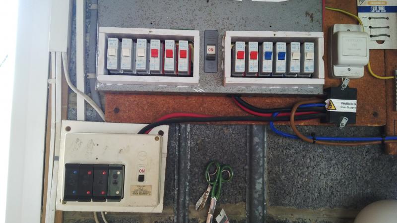
Main board
Main incoming supply on right. Main RCD for house across top. Fuse box for outbuilding bottom left
You can see the old fusebox that will be removed, the existing Henley with 3 (currently) tails out going to main home CU, fusebox and (new 16mm) tails to Solar PV system.
What you can't see on this photo is an old switch at th top which isolates teh whole system from the incoming mains. It's not a modern RCD/switch isolator, just an up/down switch.
I suppose the question is whether (in effect) 2 cores of the 10mm2 SWA can be connected directly to the Henley or it must go through another switch/isolator (which the electrician seems to have left out)??
It was constructed of two small rooms, a shower room and a pump room, each with its own light. While we were doing the roof we took the opportunity to extend it slightly, moving the end walls by just over a metre and inserting a third small room in the middle.
You've got a shower room and a pump room? That's got to be a hell of a power shower.
You've got a shower room and a pump room? That's got to be a hell of a power shower.
Heh heh, 13,000 gallons worth.
")
Actually, looking at that diagram, it needs to be 25mm SWA to export main s to the other end, doesn't it?
If I understand your proposal correctly, you're going to need a switch-fuse in the feed to the SWA going to the poolhouse and also possibly one in the feed to the 'boiler room'. The RCD for the filler pump could be in the poolhouse. However, I'm sure the electrician will understand all these requirements.I suppose the question is whether (in effect) 2 cores of the 10mm2 SWA can be connected directly to the Henley or it must go through another switch/isolator (which the electrician seems to have left out)??
Kind Regards, John
If I understand your proposal correctly, you're going to need a switch-fuse in the feed to the SWA going to the poolhouse and also possibly one in the feed to the 'boiler room'.
A switch-fuse or a fused switch, or are they the same thing? (as they seem to be £20 or £80) http://www.tlc-direct.co.uk/Main_Index/Distribution_and_Switchgear_Index/Switchfuse_SP_and_N/
There is no feed in the boiler room, just a loop on the filter pump circuit for the timer.
What does that do then? If it feeds to a 100A RCD in the CU at the other end, or does it just protect the other end of the cable?
The RCD for the filler pump could be in the poolhouse.
I think it needs to be in the garage, as it has to connect to the timer, otherwise he then needs to run another cable all the way back to the boiler house to go through the timer (the timer is connected to a pump on the central heating system which pushes the hot water through the heat exchanger for the swimming pool).
However, I'm sure the electrician will understand all these requirements
Yep, yep, will be going through it with him carefully before I get out the credit card! Just want to understand it properly first (I like to learn, but my wife doesn't trust me to cut sandwiches, let alone play with electrics, so I am the 'theory' department). I'm not seeing him until next week, and I'm budgetting...
same thing - a combination of a (simple,manual) switch and a fuse.A switch-fuse or a fused switch, or are they the same thing?If I understand your proposal correctly, you're going to need a switch-fuse in the feed to the SWA going to the poolhouse and also possibly one in the feed to the 'boiler room'.
Unless I'm misunderstanding the nature of the box labelled "63A RCD for filter pump only" (see below), there is no over-current protection on whatever is going into the boiler room other than the supplier's service fuse.There is no feed in the boiler room, just a loop on the filter pump circuit for the timer.
An RCD, per se, offers no protection against over-current (only against leakages to earth) and, in any event, it is downstream of the SWA. If the connection between the supply and a CU is more than 2-3 metres in length, a fuse (other than the supplier's service fuse) upstream of that connection is required.What does that do then? If it feeds to a 100A RCD in the CU at the other end, or does it just protect the other end of the cable?
As above, I may be misunderstand what's going on - in particular what is happening in that box labelled "RCD" - does it perhaps contain MCBs? Whatever, as I've said, whatever is going on in the boiler room needs to be protected by an upstream fuse (or MCB).I think it needs to be in the garage, as it has to connect to the timer, otherwise he then needs to run another cable all the way back to the boiler house to go through the timer (the timer is connected to a pump on the central heating system which pushes the hot water through the heat exchanger for the swimming pool).The RCD for the filler pump could be in the poolhouse.
Kind Regards, John
Unless I'm misunderstanding the nature of the box labelled "63A RCD for filter pump only" (see below), there is no over-current protection on whatever is going into the boiler room other than the supplier's service fuse.
Ah, yes, I see that now. So a switchfuse would be expected to go between the mains feed and the 63A RCD (the small CU in the garage) as over-current protection?
This is a self contained circuit which runs:
Mains > 2 way CU (63A RCD, 16A and 32A MCB) > loop on 32A MCB to boiler house for timer > 25m of SWA to poolhouse > switch > filter pump.
The timer has to be there, as it is connected to the heating pump.
An RCD, per se, offers no protection against over-current (only against leakages to earth) and, in any event, it is downstream of the SWA. If the connection between the supply and a CU is more than 2-3 metres in length, a fuse (other than the supplier's service fuse) upstream of that connection is required.
Yes, if he says we can do what I am proposing, then the supply would run 25 metres before the poolhouse CU (in which case it presumably needs to be 25mm SWA to carry that sort of load all the way, and a switchfuse once it gets there, prior to going in to the CU?)
This is a different circuit which goes:
Mains > (not sure yet... was thinking to connect it directly to 2 cores of the SWA, but the existing is 10mm and I think it needs to be 25mm to carry the full mains safely(?) > CU in pumproom (100A RCD leading to 6A (lights), 40A (sauna), 16A (sockets - might do away with the sockets), 40A (shower)
As above, I may be misunderstand what's going on - in particular what is happening in that box labelled "RCD" - does it perhaps contain MCBs? Whatever, as I've said, whatever is going on in the boiler room needs to be protected by an upstream fuse (or MCB).
Ah, my drawing. The label that reads '63A RCD for filter pump only' relates to the small 2 way CU in the garage, not anything in the boiler room. There is no RCD in the boiler house; just a loop on the pump circuit that goes to a timer and back to the CU (32A MCB) in the garage
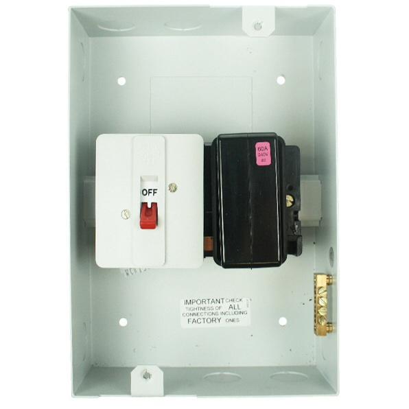
I was taught a switch fuse is an isolator and a fixed fuse in an enclosure such as this wylex one.
And a fused switch actually moves the fuses to make or break the circuit like this one.
Not that it really matters...
And a fused switch actually moves the fuses to make or break the circuit like this one.
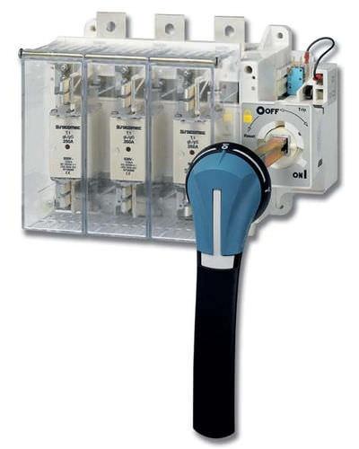
Not that it really matters...
Not necessarily, in view of what you now tell us about that box labelled "63A RCD", namely ...Ah, yes, I see that now. So a switchfuse would be expected to go between the mains feed and the 63A RCD (the small CU in the garage) as over-current protection?Unless I'm misunderstanding the nature of the box labelled "63A RCD for filter pump only" (see below), there is no over-current protection on whatever is going into the boiler room other than the supplier's service fuse.
Given that it's a mini-CU with MCBs, if it's close enough to the supply (which it probably will be), you wouldn't need the switch-fuse I've been talking about, BUT ........ This is a self contained circuit which runs:
Mains > 2 way CU (63A RCD, 16A and 32A MCB) > loop on 32A MCB to boiler house for timer > 25m of SWA to poolhouse > switch > filter pump.
The timer has to be there, as it is connected to the heating pump.
I'm confused as to where this SWA is coming from. In your diagram, it appears out of the mini-CU in the garage. From what you've said above, it sounds as if it doesn't go through any MCB in that mini-CU. If that's the case, then that one would need a switch-fuse.Yes, if he says we can do what I am proposing, then the supply would run 25 metres before the poolhouse CU (in which case it presumably needs to be 25mm SWA to carry that sort of load all the way, and a switchfuse once it gets there, prior to going in to the CU?) This is a different circuit which goes:
Mains > (not sure yet... was thinking to connect it directly to 2 cores of the SWA, but the existing is 10mm and I think it needs to be 25mm to carry the full mains safely(?) > CU in pumproom (100A RCD leading to 6A (lights), 40A (sauna), 16A (sockets - might do away with the sockets), 40A (shower)
This is getting complicated/confusing - so, as I said, I think you really need to sit down with your electrician and work out what is needed.
Kind Regards, John
Yes, if he says we can do what I am proposing, then the supply would run 25 metres before the poolhouse CU (in which case it presumably needs to be 25mm SWA to carry that sort of load all the way, and a switchfuse once it gets there, prior to going in to the CU?) This is a different circuit which goes:
Mains > (not sure yet... was thinking to connect it directly to 2 cores of the SWA, but the existing is 10mm and I think it needs to be 25mm to carry the full mains safely(?) > CU in pumproom (100A RCD leading to 6A (lights), 40A (sauna), 16A (sockets - might do away with the sockets), 40A (shower)
I'm confused as to where this SWA is coming from. In your diagram, it appears out of the mini-CU in the garage. From what you've said above, it sounds as if it doesn't go through any MCB in that mini-CU. If that's the case, then that one would need a switch-fuse.
The way I was drawing it, the 4 core SWA is attached to the small CU in the garage. 2 of the cores take the outlet from this CU to the filter pump. This circuit only runs the filter pump because it has to go to the timer.
The other 2 cores just take power directly to the other CU in the pumproom.
So, 2 cores go through the mini CU (and MCB within that) in the garage. The other 2 cores directly go to the pumproom where they go through the other CU (and MCBs within that) which feeds the lights, sauna, sockets...
Two different circuits, making use of the 4 cores in the SWA as two pairs.
The only reason for splitting them was because the pump circuit needs to attach to the timer.
Given that it's a mini-CU with MCBs, if it's close enough to the supply (which it probably will be), you wouldn't need the switch-fuse I've been talking about...
I'm curious now why proximity to the supply would mean it wasn't necessary...?
OK, I think I may now understand. The two cores going to the pumproom are simply 'passing through' that mini-CU, from the supply to the CU in the pumproom - is that correct? If so (a) those cores would need switch-fuse protection and (b) given the size of SWA you are thinking aout, there's no way that you are going to be able to do that wiring within a standard 'mini-CU, if that's what we are talking about - at the least, you would need a decent sized one. However, in view of the need for a swith-fuse, an alternative arrangement would probably be used - e.g. terminating the SWA in another box and taking feeds to that from (a) the mini-CU and (b) from the Henleys, via switch-fuse (for the supply to the poolroom CU).The way I was drawing it, the 4 core SWA is attached to the small CU in the garage. 2 of the cores take the outlet from this CU to the filter pump. The other two cores just take power directly to the other CU in the pumproom.I'm confused as to where this SWA is coming from. In your diagram, it appears out of the mini-CU in the garage. From what you've said above, it sounds as if it doesn't go through any MCB in that mini-CU. If that's the case, then that one would need a switch-fuse.
So, 2 cores go through the mini CU (and MCB within that) in the garage. The other two cores go to the pumproom where they go through the other CU (and MCBs within that).
Two different circuits, making use of the 4 cores as two pairs.
If, as in the normal domestic installation, the distance from the supply (meter) is less than 2-3 metres, then additional protection of that cabling is not deemed necessary. However, if the distance from supply to CU is longer than that, fuse protection is considered necessary.I'm curious now why proximity to the supply would mean it wasn't necessary...?Given that it's a mini-CU with MCBs, if it's close enough to the supply (which it probably will be), you wouldn't need the switch-fuse I've been talking about...
Kind Regards, John
DIYnot Local
Staff member
If you need to find a tradesperson to get your job done, please try our local search below, or if you are doing it yourself you can find suppliers local to you.
Select the supplier or trade you require, enter your location to begin your search.
Please select a service and enter a location to continue...
Are you a trade or supplier? You can create your listing free at DIYnot Local
Similar threads
- Replies
- 13
- Views
- 1K
- Replies
- 20
- Views
- 3K