
my manrose extractor fan suddenly stopped so bought this new one on opening Found no wiring to connect to a terminal block so was planning on using the existing thin wiring from the terminal block to the transformer aee attached picture of New and existing installation

You are using an out of date browser. It may not display this or other websites correctly.
You should upgrade or use an alternative browser.
You should upgrade or use an alternative browser.
manrose extractor fan
- Thread starter misterboumsong
- Start date
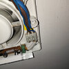
If the internal wiring connections are missing return the item and don't use it. The wiring into L SL and N is from the old cable.
Blup
Not sure I agree with this. There are connections that are useable on the new fan
As far as I can see the internal connections and wiring are all there, but the OP seems convinced otherwise, or is confused.Not sure I agree with this. There are connections that are useable on the new fan
Blup
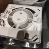
The connectors on the end of the timer PCB are, as usual, present, and could be used for connection of the supply (provided the conductors would fit into those small terminals), but what I presume is intended (as in the OP's old fan, and has been the case in every other Manrose fan I've seen) is that those small terminals are connected by ('thin') wires to a bit of normal-sized 'chock-block' for connection of the supply cable.Not sure I agree with this. There are connections that are useable on the new fan
The connectors on the end of the timer PCB are, as usual, present, and could be used for connection of the supply (provided the conductors would fit into those small terminals), but what I presume is intended (as in the OP's old fan, and has been the case in every other Manrose fan I've seen) is that those small terminals are connected by ('thin') wires to a bit of normal-sized 'chock-block' for connection of the supply cable.
Maybe you need to look in upto date Manrose fans
Maybe, but one I bought a few weeks ago was as I have described - although, admittedly,I didn't try (had no need) to ascertain the date of manufacture.Maybe you need to look in upto date Manrose fans
yes that's exactly what I mean. i have 2 supply heavier cables into a chock block. so i was just planning on using the same thinner wires drom the block to the timer pcb.The connectors on the end of the timer PCB are, as usual, present, and could be used for connection of the supply (provided the conductors would fit into those small terminals), but what I presume is intended (as in the OP's old fan, and has been the case in every other Manrose fan I've seen) is that those small terminals are connected by ('thin') wires to a bit of normal-sized 'chock-block' for connection of the supply cable.
surprised though there's no wires already from the PCB or any in the box though understand that maybe the main supply can go into here
Do that.so was planning on using the existing thin wiring from the terminal block
Otherwise it's trying to shove the rigid wiring into the tiny terminals which is likely to lead to breakage.
Indeed, if you want to keep with that one (rather than trying to get it swapped fro one which does have the chock block), I think that would be the only sensible course. As has been said, trying to get 'stiff' T+E conductors into those terminals could easily result in that timer PCB getting 'cracked'.yes that's exactly what I mean. i have 2 supply heavier cables into a chock block. so i was just planning on using the same thinner wires drom the block to the timer pcb.
I'm also surprised and, despite the suggestion that 'up-to-date' ones may be different, I've personally never seen a Manrose fan without a bit of chock block.surprised though there's no wires already from the PCB or any in the box though understand that maybe the main supply can go into here
Kind Regards, John
DIYnot Local
Staff member
If you need to find a tradesperson to get your job done, please try our local search below, or if you are doing it yourself you can find suppliers local to you.
Select the supplier or trade you require, enter your location to begin your search.
Please select a service and enter a location to continue...
Are you a trade or supplier? You can create your listing free at DIYnot Local