Nest 3rd Generation Thermostat wiring Help needed!

Joined
7 Sep 2019
Messages
3
Reaction score
0
Location
Carterton/Oxfordshire
Country
United Kingdom
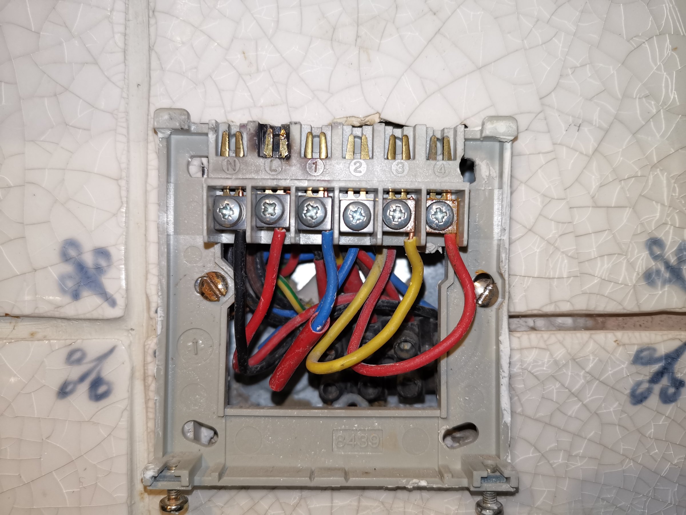
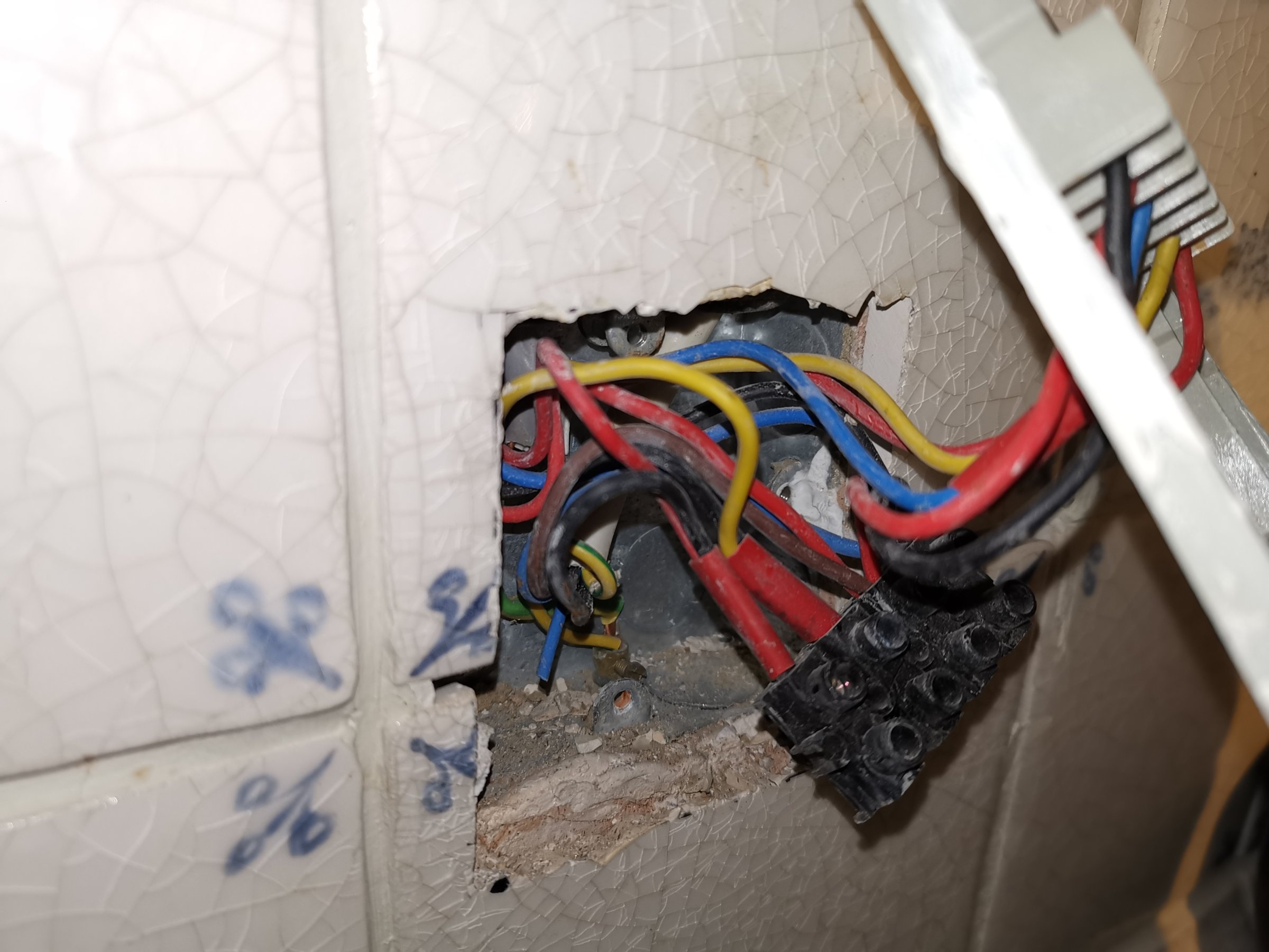
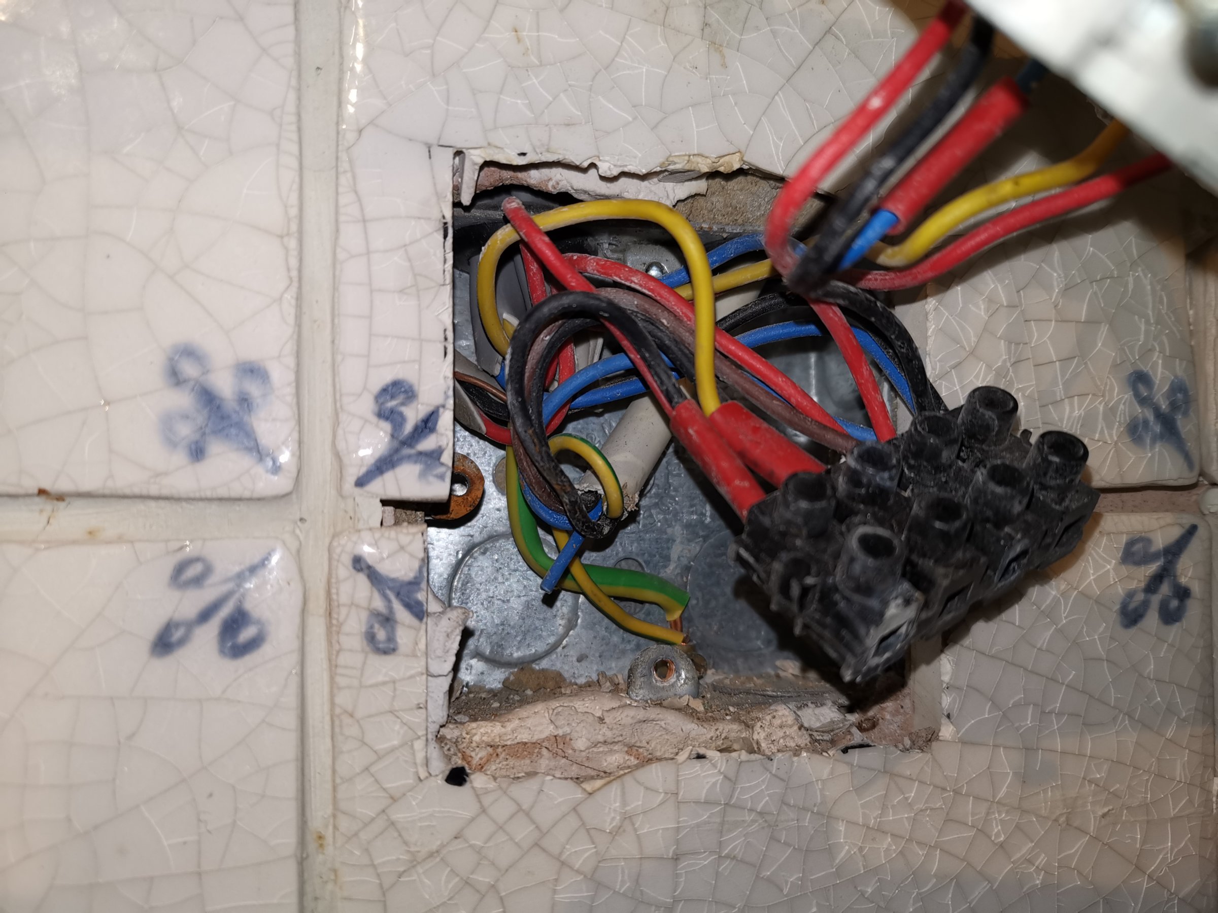
Hi Guys, I need help installing Nest 3rd Gen Thermostat wiring using existing wiring.

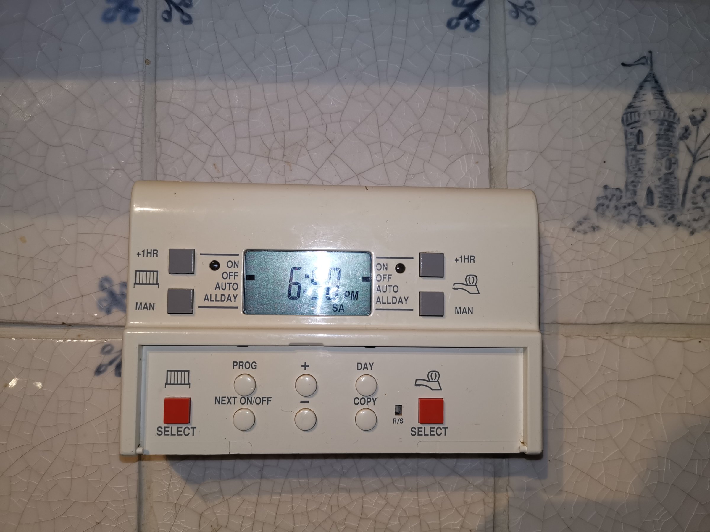
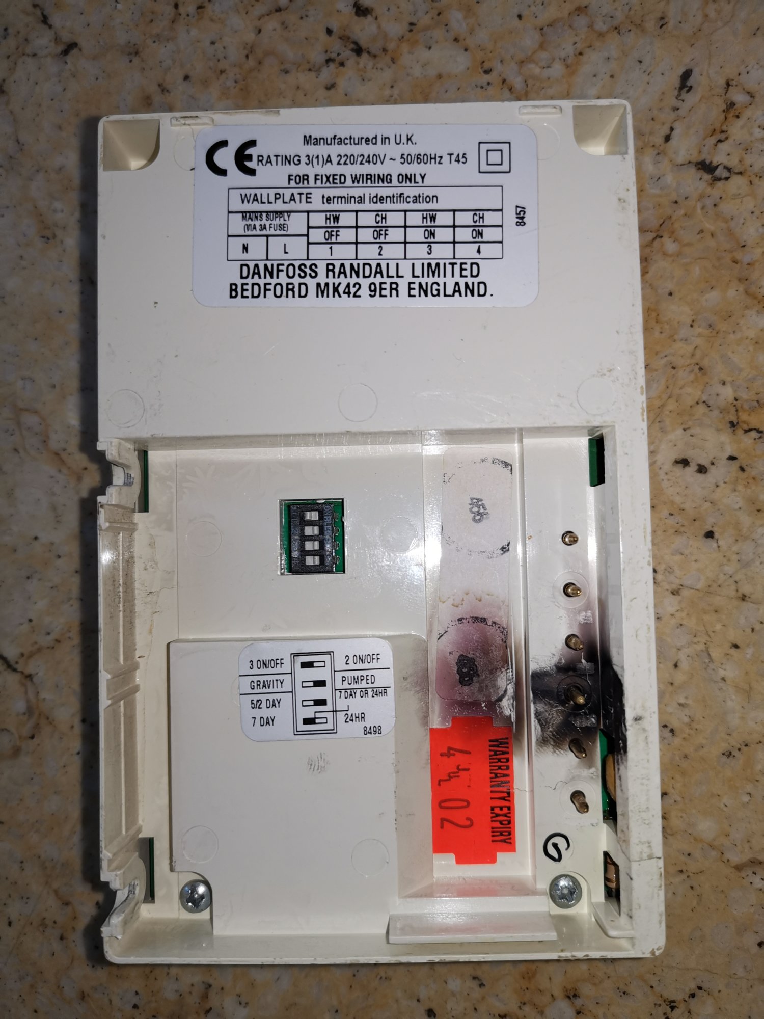
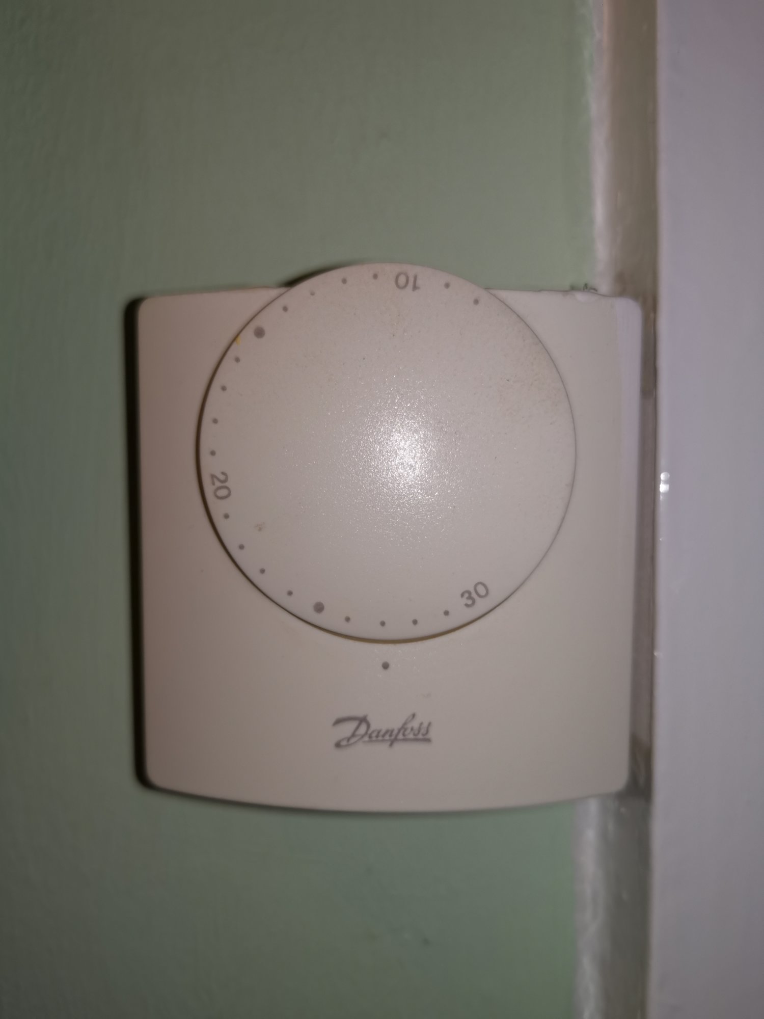
Currently on Danfoss thermostat and nest installation guide is confusing. I believe our boiler system is in Y plan.

Our Boiler is Worcester Greenstar Ri and I believe it is combi boiler. Water heats up in the stored tank.

Our current Danfoss thermostat switches on water heating automatically everyday in the morning for 1 hour and if we require more hot water we switch on water heating manually for 1 hour. And central heating works same way; if we require heating we switch on central heating for 1 hour.

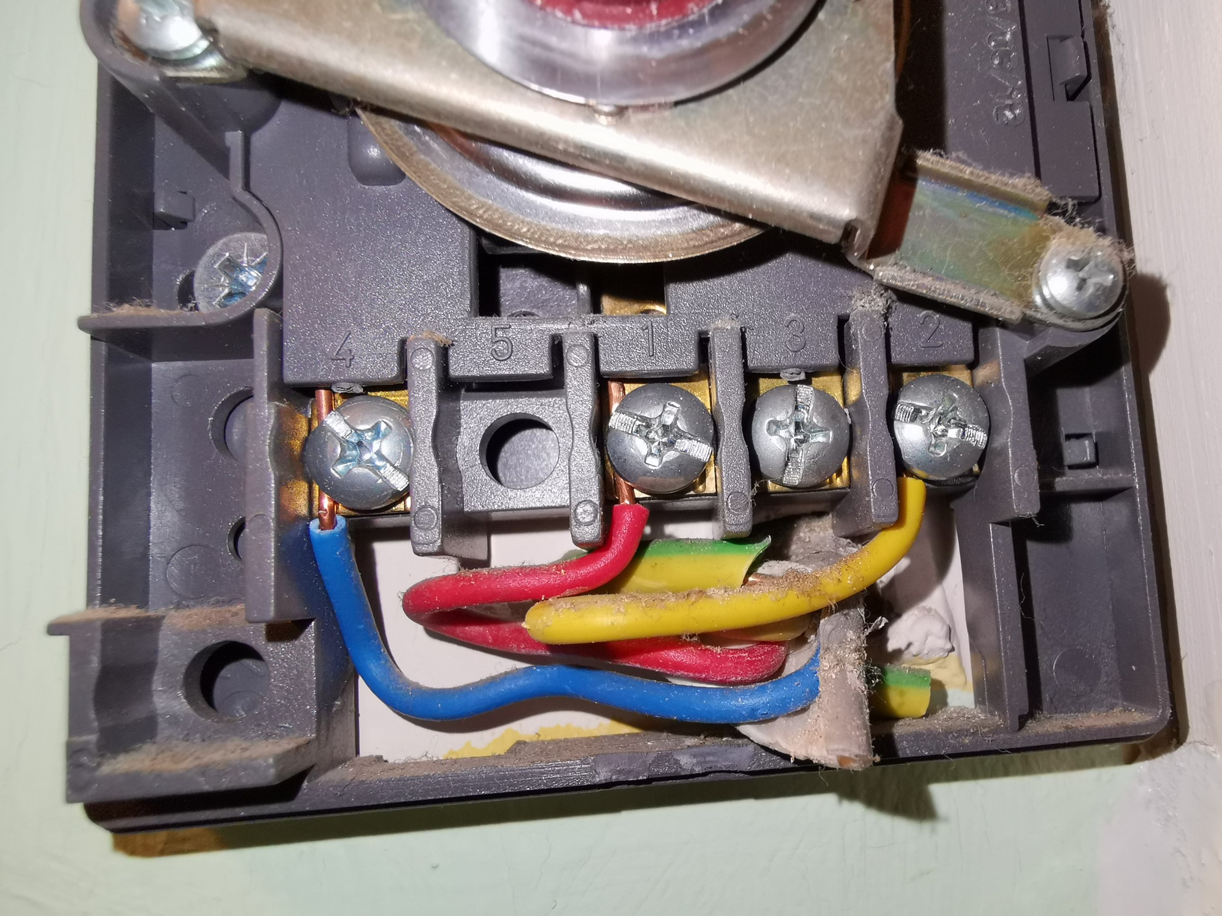
So need help in wiring Nest 3rd Gen Heat link first & then thermostat ring on existing wired thermostat.


Last edited:
Sponsored Links
Is it Y plan or combi boiler, can't be both. Nest Gen 3 has a row of terminals that will do nearly anything.
N and L power the Heat Link to N and L from Danfoss also link L to 2 and 5 on Nest
1 is likely not used.
2 and 3 turn on central heating. So 4 on Danfoss goes to 3 on Nest.
4 is only used when no tank thermostat so likely not used.
5 and 6 turns on domestic hot water. So 3 on Danfoss goes to 6 on Nest
OT1 and OT2 only used with opentherm boilers so likely not used.
Earth only required if using the 12 volt DC power
T1 and T2 feed the thermostat and works coms if required, you can use a USB and wifi instead.

On old thermostat put yellow and red in the same terminal.

You may be able to remove old thermostat, but you would need to find the wiring centre and work out which wires feed it, you may also find the terminals on Nest are too small to get links L to 2 and 5 so may need some form of wiring centre or chock block so you have three line wires one for each hole.
 
Not a combi

Can see this one could end in tears
The flash at the back of the Danfos and rats nest underneath. Thrown in the Y plan into the equation and a Nest purchased ( I see this unit as a fashion item, have yet to see Honeywell or Danfoss for sale at John Lewis) not a good combination
 
Sponsored Links
Not a combi

Can see this one could end in tears
The flash at the back of the Danfos and rats nest underneath. Thrown in the Y plan into the equation and a Nest purchased ( I see this unit as a fashion item, have yet to see Honeywell or Danfoss for sale at John Lewis) not a good combination
Since he does not know if Combi or Y plan it could also be C, S, or W plan as well. I will admit when I came to fit Nest it was not as straight forward as one is lead to believe, good point Nest will come (I would think with a charge) and sort it all out for you, however before I even started I spent a day may be more working out what I have and drawing out a wiring diagram which I could then follow, including the wiring centres used.

Even after carefully drawing out the diagram it still did not work as expected, it fired up boiler when not expected, which turned out to be the anti legionnaires software, but still not easiest to set up.

And that's for me with a degree in electrical engineering when my job was programming PLC's.

As said the burn marks do not look good.

Yes you could use one of the plans as well as using as a combi boiler, to allow things like independent control of a granny flat for example, and in real terms the combi boiler likely uses a W plan within the box, however this would be rather specialist, and not really some thing for the DIY guy.
 
  • Thanks
Reactions: DP
Where you want a single boiler to work many independent areas motorised valves are used, may be not the best way of doing it, but it is done. I see no reason why a Y plan or W plan could not be used for two centrally heated areas in the same way as used to heat water and run central heating.

I have a modified C plan instead of using a tank thermostat with NO and NC contacts I have used the contacts within the heat link. As to if anyone who came to work on it in the future could work it out is another question.

It takes time to test and build up a circuit diagram, and I think it's unlikely anyone could with a forum do much more than already done. But likely we have scared him off and we will not see him again.
 
I am very confused now, is my system is Y, T & W :(

In our airing cupboard up stairs, where we have a hot water tank; near to that we have 3 port zone valve.
 
Last edited:
I am very confused now, is my system is Y, T & W :(

In our airing cupboard up stairs where we have a hot water tank near we have 3 port zone valve.

Going by the wires in picture 1, I would hazard it is a Y plan
 
First of all a fault has occurred somewhere at sometime causing a short circuit as the burnt connections show. If the fault is still present, it needs to be rectified first. Once that is sorted the nest can be installed as follows:

Your current programmer wiring connections are:

Existing.JPG


All of the wires in the existing programmer are moved to the terminals at the Nest Heat link that have exactly the same function.

Nest.jpg


So:
The L & N are straightforward and marked the same at both the Danfoss and Nest
The wire in Danfoss HW off 1 = Nest 4 hot water satisfied
The wire in HW on 3 = Nest 6 hot water call for heat
The wire in CH on 4 = Nest 3 heating call for heat

The Nest then requires terminals L, 2, and 5 to be linked together (The Danfoss has these connections already made internally)

Finally the old thermostat needs decommissioning so that it doesn't interfere with the Nest. If you are happy to leave the old thermostat on the wall, the easiest way is to move the yellow wire from terminal 2 and put it in terminal 1 with the red wire.

Alternatively trace the thermostat cable back to its origin and note where the yellow and red wires are connected. then disconnect the cable completely and remove it along with the old thermostat. Then link together the terminals where the red and yellow wires have just been removed from.

You can use Nest Heat link terminals T1 & T2 to connect to the Nest thermostat to provide it with 12V power, or alternatively use a separate plug in power supply for the thermostat
 
Thanks Stem, I will follow your guidelines and get back to you. Once it's successfully done I will upload the actual heat link with wiring connections so that everyone get to know.
 

DIYnot Local

Staff member

If you need to find a tradesperson to get your job done, please try our local search below, or if you are doing it yourself you can find suppliers local to you.

Select the supplier or trade you require, enter your location to begin your search.


Are you a trade or supplier? You can create your listing free at DIYnot Local

 
Sponsored Links
Back
Top