• Looking for a smarter way to manage your heating this winter? We’ve been testing the new Aqara Radiator Thermostat W600 to see how quiet, accurate and easy it is to use around the home. Click here read our review.

Nest 3rd thermostat install

Joined
7 Oct 2015
Messages
31
Reaction score
5
Country
United Kingdom
Hi,

Apologies for yet another Nest installation post! Just purchased a 3rd gen to go with our new boiler (Valliant ecofit sustain) and wondering whether installing it is a DIY job?

I'm fairly competent with basic electrical work but could do with a bit of help with this one, I'm a bit overwhelmed with the wires! More than happy to get a spark in if required!

Current setup is a Grasslin QEG-2 programmer and Honeywell stat.

Cheers
 

Attachments

  • IMG_5194.png
    IMG_5194.png
    979.7 KB · Views: 83
  • IMG_5195.png
    IMG_5195.png
    748.9 KB · Views: 72
  • IMG_5196.png
    IMG_5196.png
    741.7 KB · Views: 72
  • IMG_5197.png
    IMG_5197.png
    787.7 KB · Views: 83
Usually, we can guide you through mapping over the wiring from your old programmer to the Nest Heatlink.

However, in your case, there are a couple more wires behind the programmer, than there may normally be.
To compound this, the wiring terminals within the Heatlink are quite small - it can be tricky to fit more than a couple of wires into them.
Does your existing programmer actually control timing of the C/H, or is it purely controlled by the thermostat?

What are you planning to do with the Nest thermostat - would you like it mounted on the wall, where the existing stat is, or is it going to be stand-alone, powered from a USB supply?

If you can post a picture of the wiring within your wiring centre, we may be able to work out what's going on.

And just to mention, if you felt like returning the Nest, a dual channel Drayton Wiser, or Hive system would be a straight swap for your existing programmer, the existing stat could then be left set to maximum, or bridged out.
 
As to if DIY or need an electrician, can't help, depends on your ability. However, I would say the Nest does not have much room in it. So may need a wiring centre or junction box next to it.
1738015126588.png
But the Nest connections are shown here. It will also need two links, L to 2 and 5.

It would be nice to reuse the wires to the old thermostat, but can't see where they go to reuse them, and Nest thermostat will work with a USB power supply.

Personally disappointed in Nest Gen 3, was told before buying it would work with Energenie, it seems when Google took over Nest, this stopped. For the USA market there are sensors, but not released for UK market. So now I have Wiser running in parallel with Nest, so I can have sensors in other rooms.

One of the main reasons why people use Wiser, Nest, EvoHome etc. Is they have the option to connect to boiler using OpenTherm, I can't use this option as boiler not enabled.

If paying good money to have better controls installed, I would question if Nest is best option.
 
Thanks both.

The amount of wires are indeed what caused me the most confusion - albeit there is a fused spur that isolates both the boiler and the programmer, so I'm not sure whether that accounts for them? I'd have to do some testing.

The reason we went with nest was solely the price (next to nothing) and unfortunately, no option to return.

To answer your questions, the current programmer does control timings for both the HW and CH. My intention was to replace the programmer with the heatlink and the wall thermostat with the nest if that's possible.

Would it be an option to install a JB over the old programmer, then wago a couple of flexis to the heatlink?

Photo of the wiring centre is attached. Looks a mess to me!

Cheers
 

Attachments

  • IMG_5200.jpeg
    IMG_5200.jpeg
    294 KB · Views: 62
Thanks for the photo and description.

Would it be an option to install a JB over the old programmer, then wago a couple of flexis to the heatlink?
Yes, it certainly would be possible.

However, it might not help you decommission the old stat wiring, especially if you would like to reutilise those wires to provide the 12V to the thermostat from the Heatlink.

If you are interested in exploring further, I've got some guesses for where the cables from the wiring centre go, but the site is misbehaving at the moment, so I can't upload the pics...

In your pic of the wiring centre, does the black cable that goes off the top of the image go to the Hot water zone valve?
Does the lower black cable go to the C/H valve?

And where the two white flexes enter the wiring centre on the right, does the one nearest the bottom go to a pump, and the one slightly higher up and below it, go to the tank stat?

Just had a look at the wiring - you're bang on with all of your guesses!

Not sure whether it's helpful but I've attached another image of the wiring so it's a bit clearer.

Edit: just noticed I'm having the same issue re photos, will try again later.
 
I am also having an issue with photos. In a way lucky, as my boiler is in the flat under the main house, and I am not that worried about what it looks like.

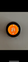
I looked at my wiring, and realised it could not have possibly worked as it was, at the three core and earth from main house to flat, changed from old to new colours, and one wire was open circuit. This was why I went for Nest Gen 3, as the two wires heat link to thermostat keeps the battery charged and controls both DHW and CH, and was claimed to work with Energenie MiHome TRV heads and I already had four.

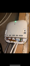
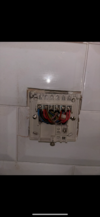
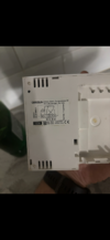
I sat down with a paint program and worked out how to wire with the existing wires, since I am using a C Plan with two pumps and two motorised valves and a relay, no point showing my wiring, as it was designed so the flat and main house could run independent but with the same boiler.

I am no good at plumbing, so got someone in to do that, and they admitted they could not wire it up, but that did not worry me. However, it did not work as planned, what I had not considered is one can adjust how fast a room heats up with the lock shield valve, but not how fast it cools, and my hall cools too slow. And the wires only go to hall, so I was left with two options.

One use a wireless thermostat, or two drop ceiling to thread new wires, yes Nest Gen 3 can be powered with USB, but the whole idea was to have all powered from the UPS supply from the solar panels, so USB does not help, needs to be primary cells to power thermostat, so will still work with a power failure.

I fitted two wiring centres/junction boxes, one by the pumps and valves, the other by the thermostat/hub/heat link, this worked out well, as when I came to add a second thermostat for the main house, it was easy. I now have Nest for the DHW and CH in the hall, and Wiser for the CH in the living room. Now I have Wiser, I can add as many thermostats or linked TRV heads as I want, should I find any room too cool.

It seems so different to last house, which was open plan, and one thermostat controlled the whole of the downstairs without a problem, and TRV's stopped upstairs over heating, every home is different, and you need to use some thought as to what you need.
 
Just had a look at the wiring - you're bang on with all of your guesses!
Now here's some more guesswork!
Here's a potential layout of your system, that would work; it's a little unusually laid out - but it does seem to match the wiring shown in your images.
A quick look behind the stat and programmer to see if the two red wires go into a double red twin and earth, may partly confirm.


Again, this is guesswork, but as you say...
I'd have to do some testing.
this may give you an idea of where to start.
 
Looks about right to me - I do have continuity between pin '1' on the thermostat and pin '4' on the programmer - but can't understand why there would be 2 separate red wires to the same terminals?

Only question now would be how would you go about wiring the stat? Would I need to connect the permanent live to the switched live with a wago behind the old stat? Then use the other red wire/earth as the 12v feed? Would that be sufficient?

Cheers
 
Looks about right to me - I do have continuity between pin '1' on the thermostat and pin '4' on the programmer
It's quite important to check this properly before taking any further advice from me!
It would really be worth checking for continuity on all four wires behind the stat to see if they really do join up as in my diagram - and to check there is no continuity to any other connections. To check properly, would mean disconnecting the wires from the terminals, so there are no alternate continuity paths.

Only question now would be how would you go about wiring the stat? Would I need to connect the permanent live to the switched live with a wago behind the old stat? Then use the other red wire/earth as the 12v feed? Would that be sufficient?
That's where it becomes complicated!
If your system is laid out as I suggest, there wouldn't be enough wires to provide the Heating switched live and the 12V supply.
It would be simpler to mount the Heatlink at the wiring centre and use the black and red cable from there to the stat, to power the Nest.
The cable connections behind the old programmer could be rationalised and a blanking plate fitted over the hole.

but can't understand why there would be 2 separate red wires to the same terminals?
The way the system has been installed (if it does follow my schematic), would mean an extra single wire was needed to connect the programmer to the stat.
There isn't much call for single and earth cables, so they may have used what they had available on the van, i.e. a bit of red and red twin and earth.
There would have been alternatives, i.e. using more triple and earth, but that would cost a bit more.
 
Thank you. I've just confirmed with testing that the other 2 wires from the stat are as per your schematic.

So if I'm understanding this correctly:

Pull L from 10
Pull N from 3

3 wiring centre - 3 Heatlink
2 wiring centre - 6 Heatlink

Black from 3 & red from 6 as 12v power source.

Thanks for your help :)
 
Pull L from 10
Pull N from 3
Yes, and as per Nest install manual, the Heatlink earth terminal should also be connected, due to the use of T1 and T2.

Black from 3 & red from 6 as 12v power source
Yes, into T1 and T2

3 wiring centre - 3 Heatlink
2 wiring centre - 6 Heatlink
6 wiring centre - 3 Heatlink
2 wiring centre - 6 Heatlink

You would also add short link wires between L and the commons 2 and 5 on the Heatlink.

And then it's just tidying up the wiring behind the old programmer, but at the least, safely isolate the double reds in a separate terminal block/wagos - 12V DC and mains don't mix well!

Good luck :)

Edit:
One more continuity test to double check, is wiring centre 10 definitely connected to permanent Live, L on the programmer?
 
Last edited:
I saw your edit after I wired everything up, but fortunately, everything seems to be working as it should - result!

I do have one issue however, I can't see where I control the timing for the HW... how do I control that with my boiler?

EDIT: Pin 3 on the old programmer is currently on its own in a wago - does that need wiring up to the permanent live?
 
Last edited:
I wired everything up, but fortunately, everything seems to be working as it should - result!
Brilliant! Well done, that was quick work! :)
Thanks for letting us know the outcome.

I can't see where I control the timing for the HW.
Have you tried...


The red wire that was in terminal 3 of the programmer should be fine left disconnected, in its own wago.
 
I figured out that the thermostat was set to 'combi' instead of 'system', so I've changed it and that's done the trick!

I'm absolutely chuffed to bits. There's absolutely no way I'd have figured this out on my own, so I'm very grateful for your assistance.

Attached some pics of the finished article, just need to tidy up the wiring and get the heatlink secured properly now!

Thanks again :)
 

Attachments

  • IMG_5224.png
    IMG_5224.png
    785.3 KB · Views: 42
  • IMG_5225.png
    IMG_5225.png
    1,009.3 KB · Views: 38

If you need to find a tradesperson to get your job done, please try our local search below, or if you are doing it yourself you can find suppliers local to you.

Select the supplier or trade you require, enter your location to begin your search.


Are you a trade or supplier? You can create your listing free at DIYnot Local

 
Back
Top