Nest heat link to Baxi Duo Tec

Joined
25 Nov 2017
Messages
7
Reaction score
0
Country
United Kingdom
Hello,

I'm after a little help on wiring a heat link into a Baxi Duo Tec 33 Combi boiler please..

There is a wireless Salus RT501RF RF (XL) installed at the minute.
Removing that is simple, it's figuring out the call for heat terminal that I'm struggling with!

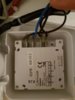
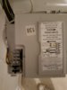
I'll and attach photos of the terminal block, I think I remove the link loop from terminals 1 and 2..

No earth required and the live and neutral go to the heat link, but what about the call for heat? (CH)?

I don't have a photo of the heat link wires on my phone (I'm at work) but I have a link loop from live to terminal 2 (Common) I believe.

Thanks in advance!
 

Attachments

  • 20171125_141333.jpg
    20171125_141333.jpg
    211.2 KB · Views: 2,680
  • 20171125_141246.jpg
    20171125_141246.jpg
    197.7 KB · Views: 2,905
Last edited:
Sponsored Links
The normal way to wire a Heatlink to your boiler is as follows:

1) The Heatlink Live & Neutral will be wired into the Live & Neutral terminals labelled 3A supply at the Baxi as shown in your second photo.
2) In the same photo, there is a yellow link wire between terminals 1 & 2. remove the link.
3) Connect terminal 2 of the Baxi (Live out) to the Heatlink terminal 2 (Common)
4) Connect terminal 1 of the Baxi (Live in) to the Heatlink terminal 3 (Call for Heat)

You don't give any details of how the Salus has been wired in normally. I would have expected that the terminals 1 & 2 where the link is would have already been used. However unfortunately model RT501RF RF (XL), doesn't mean anything to me and I can't find any information about it on line. However, if you know how to remove it, then it doesn't really matter. Just check to make sure that the wiring isn't left 'open circuit' when it is removed otherwise the Nest won't work.
 
Thanks Stem, that makes sense.

I couldn't find much on the Salus either. It has a push connector that goes straight into the PCB. Easy to remove and shouldn't leave the circuit open.

With the wiring setup you describe, do I still need the link wire from Live to terminal 2 on the heat link?

Thanks again for your help - makes more sense now.
 

Attachments

  • 20171126_235230.jpg
    20171126_235230.jpg
    160.5 KB · Views: 1,284
Sponsored Links

Sorry, for clarity, I meant the link wire in the heat link in the new photo I added.

Thanks
 
With the wiring setup you describe, do I still need the link wire from Live to terminal 2 on the heat link?

No you don't need it, if you had followed the instructions in my original post. If you had done, there would be now be 4 single, wires one each in the following terminals L, N 2 & 3, and no links.

1) The Heatlink Live & Neutral will be wired into the Live & Neutral terminals labelled 3A supply at the Baxi as shown in your second photo.
2) In the same photo, there is a yellow link wire between terminals 1 & 2. remove the link.
3) Connect terminal 2 of the Baxi (Live out) to the Heatlink terminal 2 (Common)
4) Connect terminal 1 of the Baxi (Live in) to the Heatlink terminal 3 (Call for Heat)

The (L) to (2) link at the Nest is only required when there isn't a 230V supplied from the boiler, so the link conveniently picks it up from the adjacent Nest (L) terminal. In your case, as you can see from your original photo the boiler supplies the Live from Terminal (2) 230V live out.

However, there is more than one way to skin a cat, so fortunately in this case you have been lucky, and, assuming the black wire in Nest terminal (3) goes to terminal (1) of the baxi, you have connected the live supplied by the boiler to the live terminal at the Nest, so no harm done. However if your boiler had used 24v instead of 230V for it's control circuits it would be a very different story...
 
Last edited:
No problem, I would have done exactly the same thing (y). I find it odd when someone asks for advice and then ignores it. Makes me wonder why they asked the question in the first place. :confused:
 
No problem, I would have done exactly the same thing (y). I find it odd when someone asks for advice and then ignores it. Makes me wonder why they asked the question in the first place. :confused:

Hi Stem,

Apologies, not ignoring the advice, I was on a late shift at work so I didn't have the boiler or heat link in front of me.

Prior to asking for help here I had seen a wiring setup with the link wire in the heat link, bit as you say that isn't required in my boiler.

The four wires make sense and I hooked it up that way.
The heat link and thermostat powered up, synced and seemed to be working.

However they will not control the heating. The thermostat indicates (turns screen turns orange) that it is firing up the boiler, but the boiler isn't actually doing anything.

No errors on the boiler panel, heat link or thermostat and the wires are all secure / connected.

My thought it that the wireless receiver for my current thermostat has something to do with it.

The thermostat unit is marked as a Salus RT501RF (TX). I think that may just refer to a sub-model that came packaged with the boiler.

The wireless receiver is designed to fit into the boiler where the timer would go. It has a model number of RT500BC.

The receiver has a specific push connection on the PCB, presumably where the timer would go? The push connector has L, N, NO, COM.

Simply removing the push connector totally disconnects the Salus, but I'm wondering if there is something else that needs to be done?

For now I've put the Salus unit back in to avoid the wrath of the wife if the house gets to cold!

Thanks again for any help you can provide.
 
Im thinking that removing the push connector leaves the circuit open?

Could I use a small terminal to join the two black wires for COM and NO?

Essentially the reverse of the yellow link wire in the boiler terminal 1 and 2?

Page from the Salus instructions pdf attached and image of the reverse of the Salus receiver.
 

Attachments

  • salus wiring.JPG
    salus wiring.JPG
    64.5 KB · Views: 1,088
  • 20171125_135254.jpg
    20171125_135254.jpg
    154.9 KB · Views: 1,041
Nest now fully working, thanks again for the advice.

For anyone else in a similar position with a Baxi Duo Tec boiler and a Salus RF500BC wireless thermostat and receiver, follow the below wiring instructions from Stem.

1) The Heatlink Live & Neutral will be wired into the Live & Neutral terminals labelled 3A supply at the Baxi as shown in your second photo.

2) In the same photo, there is a yellow link wire between terminals 1 & 2. remove the link.

3) Connect terminal 2 of the Baxi (Live out) to the Heatlink terminal 2 (Common)

4) Connect terminal 1 of the Baxi (Live in) to the Heatlink terminal 3 (Call for Heat)

In addition, I (eventually) left the Salus receiver in the boiler, still plugged into the PCB, but pulled and linked the two black wires (terminals 3 and 4) on the back of the Salus receiver). The receiver was then switched to manual mode.

Doing the above got me up and running.

Much easier to understand than the Nest instructions too...
 

DIYnot Local

Staff member

If you need to find a tradesperson to get your job done, please try our local search below, or if you are doing it yourself you can find suppliers local to you.

Select the supplier or trade you require, enter your location to begin your search.


Are you a trade or supplier? You can create your listing free at DIYnot Local

 
Sponsored Links
Back
Top