Old heating system with two adjacent thermostats - what?

Joined
24 Jan 2010
Messages
9
Reaction score
0
Location
London
Country
United Kingdom
I have just started investigating anew the heating setup at my girlfriend's flat. The heating system is currently bodged to use the hot water channel only of the CH controller, using the controller's timer. The zone valve does not work and is permanently in a "hot water plus CH" mode and the hot water tank stat has been removed from the tank. Thus the boiler and pump just come on when commanded to do so by the controller, heating both water and radiators.

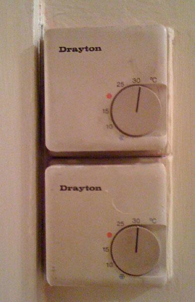
She has two currently disused room thermostats in her hall, mounted adjacent to each other. I would like to get them working again.

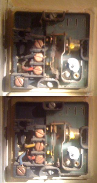
Thermostat #1 has one red and one black wire connected.
Thermostat #2 has three wire connections, maybe green yellow and red if I remember correctly.

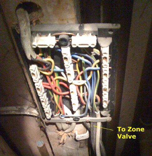
The thermostats do appear to be powered from the CH mains supply, and are still powered even if I remove the CH controller from the wall.

My initial investigation suggests that the "CH on" pin of the controller wall panel goes to 240V when both stats are turned on. When both are turned off (i.e. down) it goes to 0V. And it seemed to me to be floating around 130V when one or the other was switched on.

My best guess is that these are intended to be "day" and "night" stats with the night one overriding the timer.

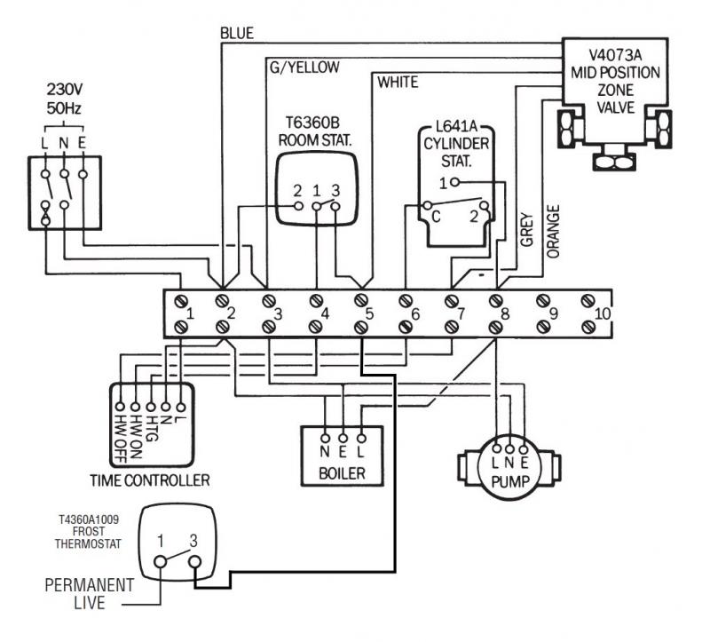
Can anyone suggest a wiring diagram that may have been used here?

Thanks!

Alan
 
could u perhaps take a couple of pictures of whats there in the wiring unit now. and also trace back to the wiring unit from the 2 stats are they both room stats or is one been used as a frost stat? and tell us what programmer is been used. the 2 port valve isnt working you say or is it not wired in n left in the manual?

Nath
 
The wiring is entirely hidden and the colours inside the stats don't seem to match the wiring in the kitchen where the controller is. I will try to take a picture of the inside of the stats and post it.

The controller is one that I installed onto the pre-existing wall mount point (it has the standard pinout to accept the pins from the back of the Drayton LP522 which I fitted). Only the HW is connected as I couldn't get the CH mode to work: probably something to do with the thermostats, with hindsight. At the time my girlfriend was claiming the stats predated the conversion of the house into flats, but this is clearly not the case as they are wired into her boiler. I think you're right - the second may be some sort of frost stat.

The only other odd thing about the installation is that in the kitchen there are two wall mount points for heating controllers, one above the other. I used the lower one, on which a broken heating controller had previously been fitted. The upper one is just blanked off but it does have some wired going to it as if in readiness for some sort of controller. Perhaps there were once two separate analogue timers, one for water, one for CH?

I'm not sure if the zone valve is disconnected or just broken. I will try to have a look but I believe the history was that something broke and would have been quite expensive to fix (£200?), the system was left limping along with both zone valve ports open and all room/tank thermostats disabled. I should try to find out what is actually broken though, as it is remotely possible that it was a controller problem all along (and I have now replaced this).

Is a frost stat a fairly standard thing to use and how would it normally be connected?

Cheers

Alan
 
Frost stats are used to protect boilers and pipework installed in vunerable areas. It should be wired as to 'bypass' the clock, with the input being permanently live when the electrical supply to the entire system is on. Then, should the temperature drop too low during an idle period on the system (i.e. clock is set for 'off' overnight), the frost stat will override the timer and fire the boiler etc to prevent frost damage to boiler and/or pipework.
 
For what it's worth, here are some images.

1. The thermostats.
2. Inside the thermostats.
3. Kitchen wall plates where controller is mounted
4. Amazing junction box. The supposedly-broken zone valve is still wired in by the looks of it.

I can probably have a go at following all the wires through but I am curious to receive any advice on how the wiring should conventionally work in this sort of setup.

Thanks!
 
I've done some digging and have managed to edit together a couple of Honeywell wiring diagrams to show how a Frost Stat is supposed to be connected to a traditional Y Plan system. Full wiring diagram below.

Cheers

Alan


If you need to find a tradesperson to get your job done, please try our local search below, or if you are doing it yourself you can find suppliers local to you.

Select the supplier or trade you require, enter your location to begin your search.


Are you a trade or supplier? You can create your listing free at DIYnot Local

 
Back
Top