I'm adding a radiator and have found that the pipework wasn't as I thought it was and I'm limited on what does I can pull up to investigate further.
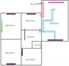
I've attached a quick drawing of the upstairs. The red lines are 22m pipes that I can see, the blue lines are 15mm pipes that I can see.
I can take up the floor in bedroom one.
I can take up the floor on the landing.
Bedroom 2 and 3 would be a pain to take up. Bedroom 4 would be nearly impossible to take up! The bathroom would also be a pain to pull up.
The purple blocks are upstairs rads.
The green blocks are to show where the rads are downstairs.
The pink block shows where I need to add a rad.
Obviously I can see the flow and return at the boiler end of things and they go off into Bedroom 4.
Bedroom 1 is an extension built about 30 years ago. The 15mm to there would have been added then which I presume joins in under bedroom 4.
The rad under bedroom 1 was added about 10 years ago, and I was under the impression it joined 22mm pipe but it doesn't. It is just tee'd off the 15mm to the bedroom 1 rad. (It all works well though)
The airing cupboard contains the cylinder. The pipework drops down and heads off into the bathroom first underneath the bath.
I could do with some advice on joining the gaps and working out where it would be best to join in to add a new radiator.
I expected to see a pair of 22mm pipes for the flow and return. Could the 15mm and 22mm pipe that run together under the landing be the flow and return? Do you have a 15mm return?
Could I tee off those pipes there in the landing and run those across into bedroom 1 and then across to the new rad? If so how far would the 22mm need to go?
If I do, do this would it be worth redoing the pipework to the rad under the garage so it doesn't tee off the bedroom rad?