

Just teared down a cheap USB power supply from a USB hub, and to no surprise  the isolation between the mains primary side and the SELV secondary side was suspicious at best.
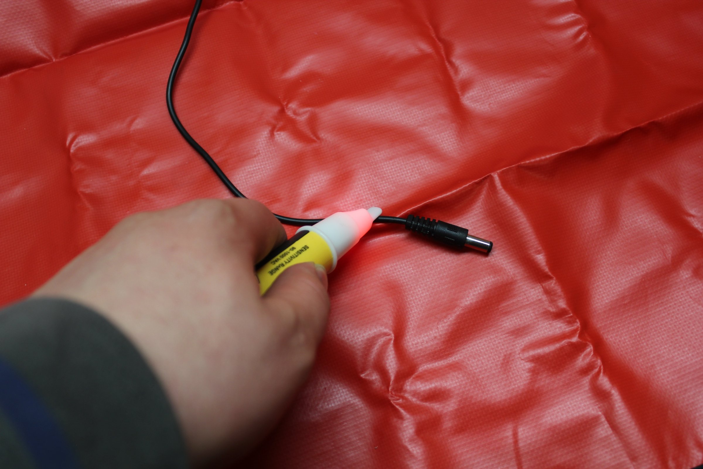
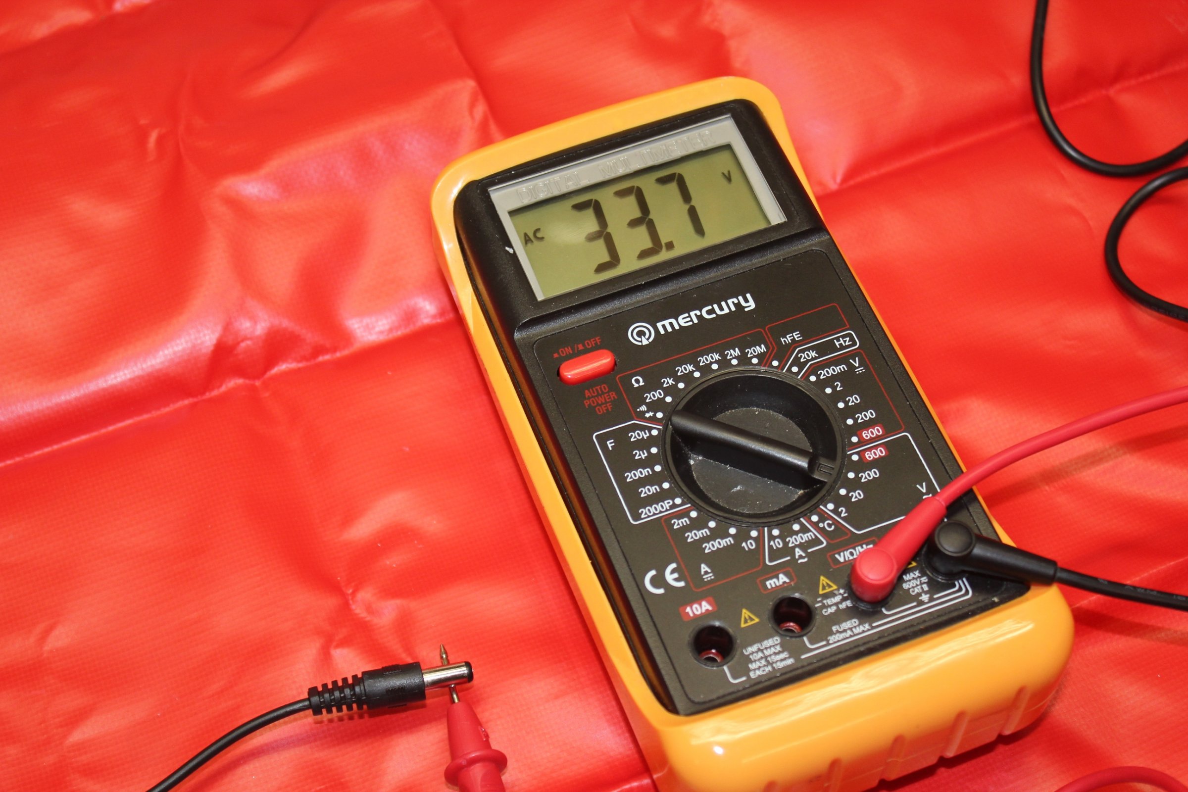
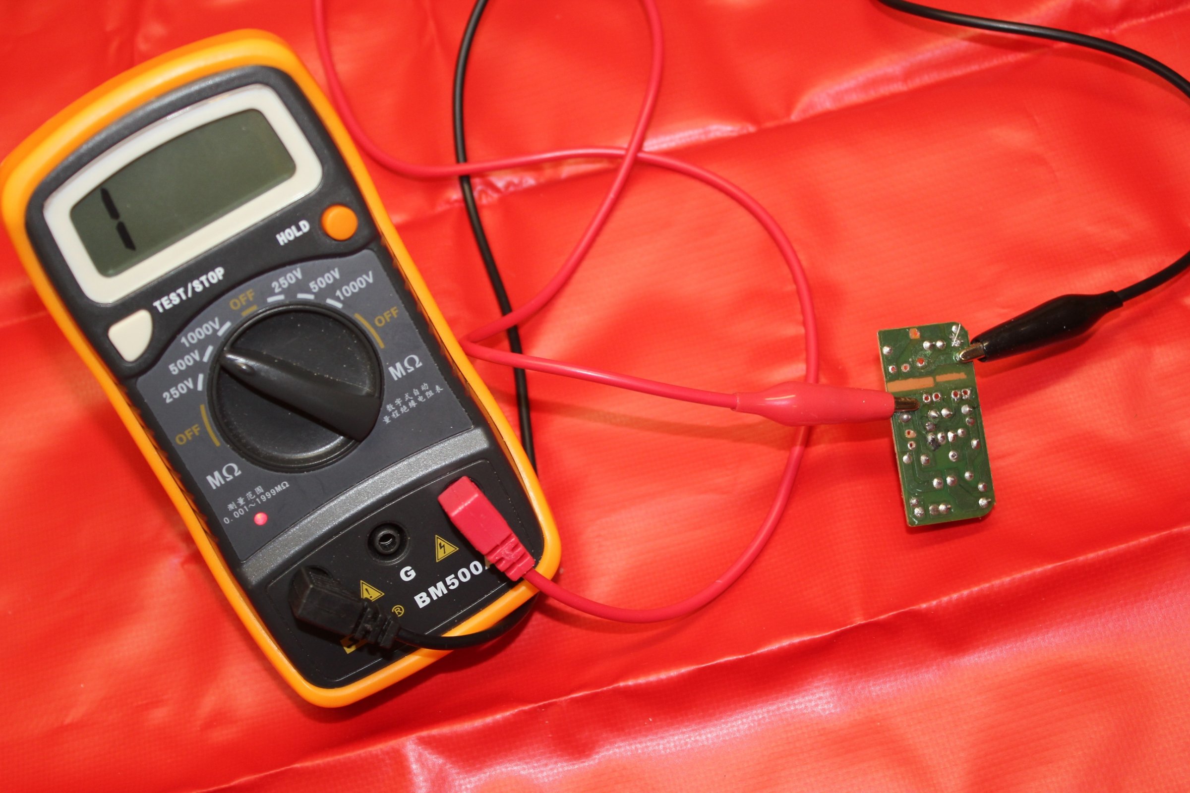
Not only did my non contact voltage detection stick react to what should have been the separated isolated 5V output , but when measured with a MM between mains earth and the 5v output jack, it displayed 33V AC.
  (Shown Below)
Non-Contact stick reacting:
33V AC between Mains Earth (COM jack on MM) and the 5V output (VΩHz jack on MM):
So following the result I got from my MM, I decided investigate the workings of the switch mode power supply.
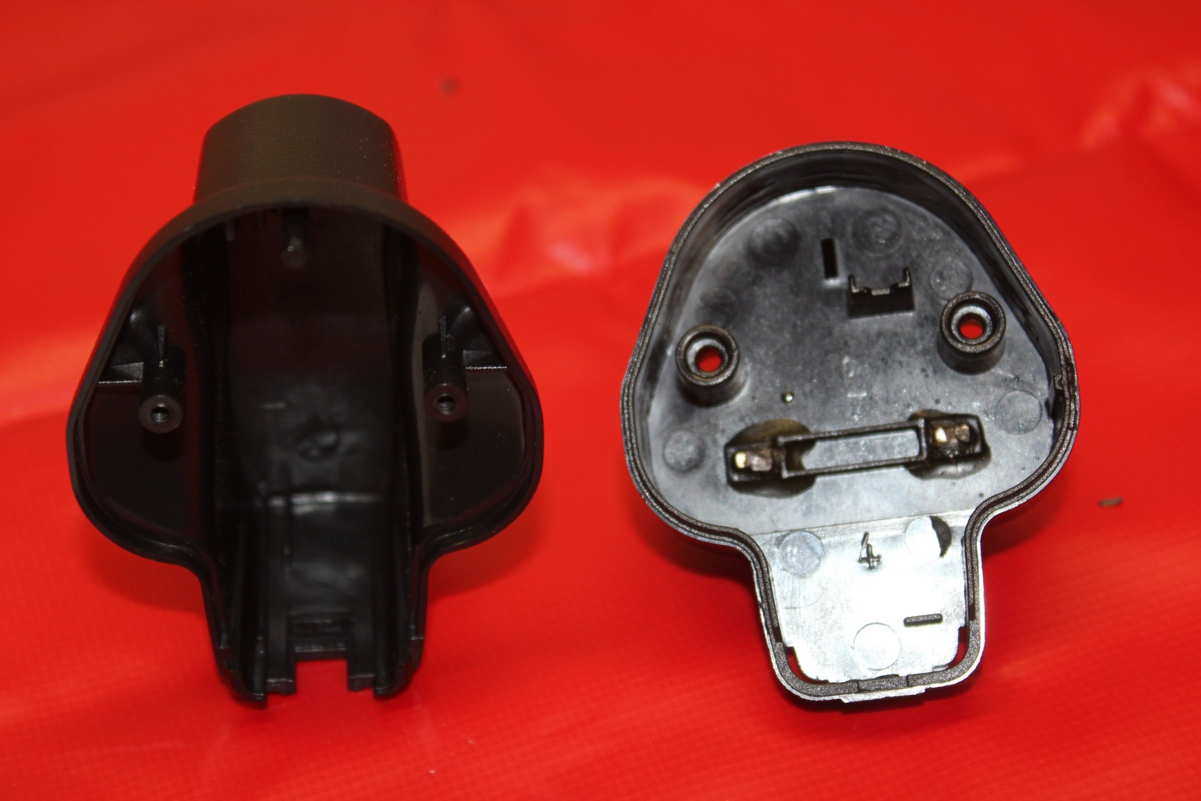
Moulded Casing:
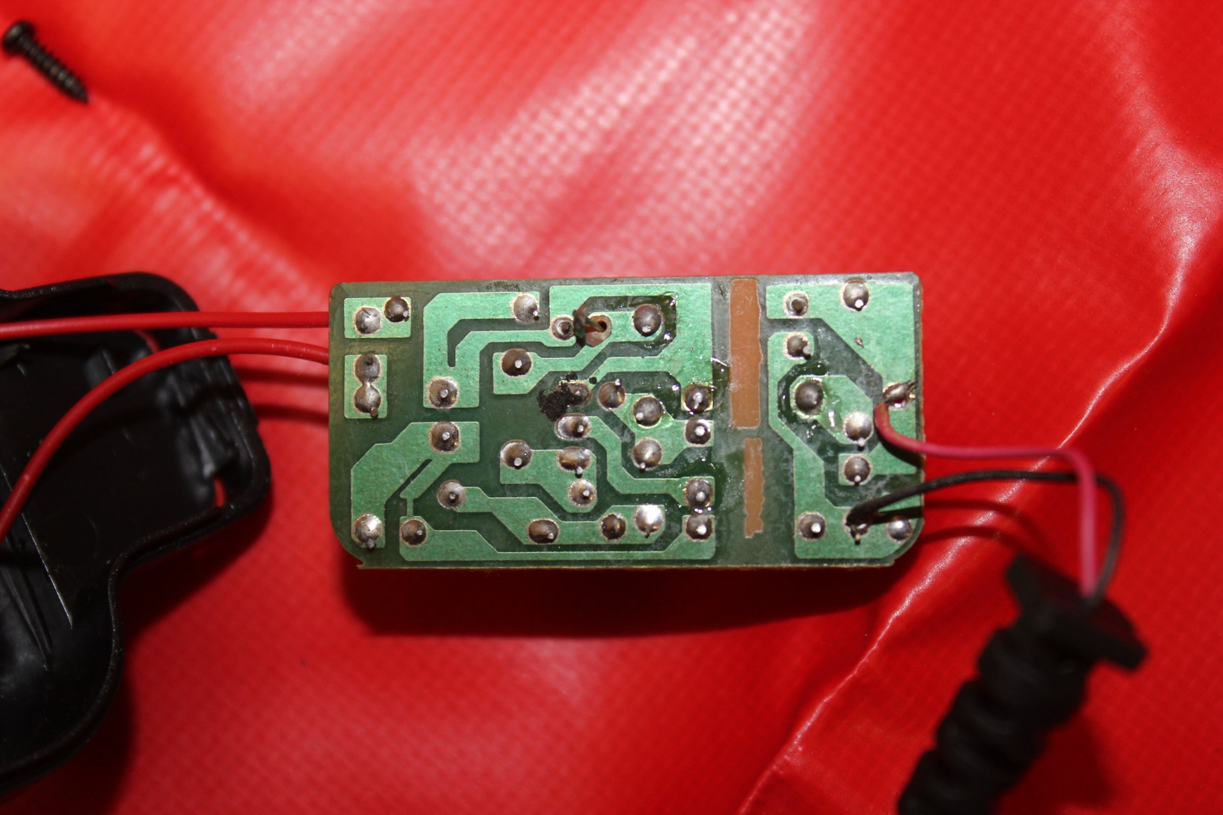
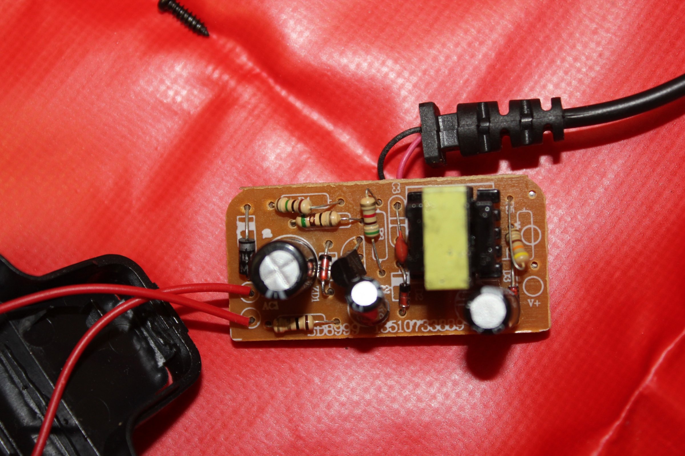
Back view of PCB: (Notice the dry solder joints!)
Front view of PCB:
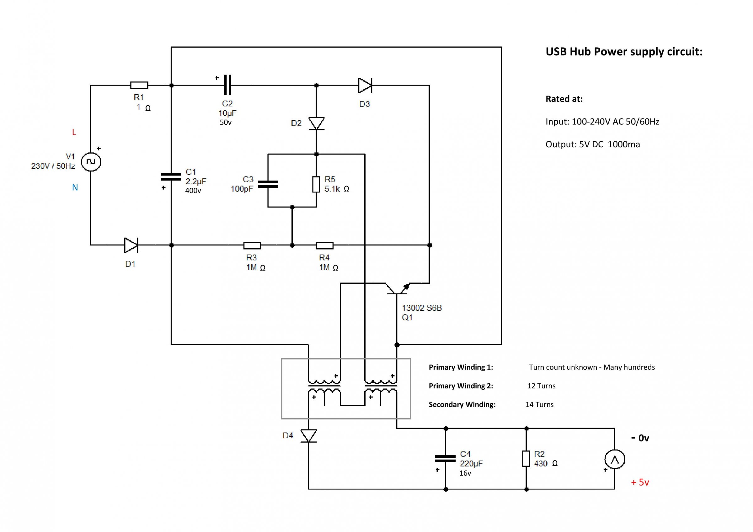
Circuit Layout:
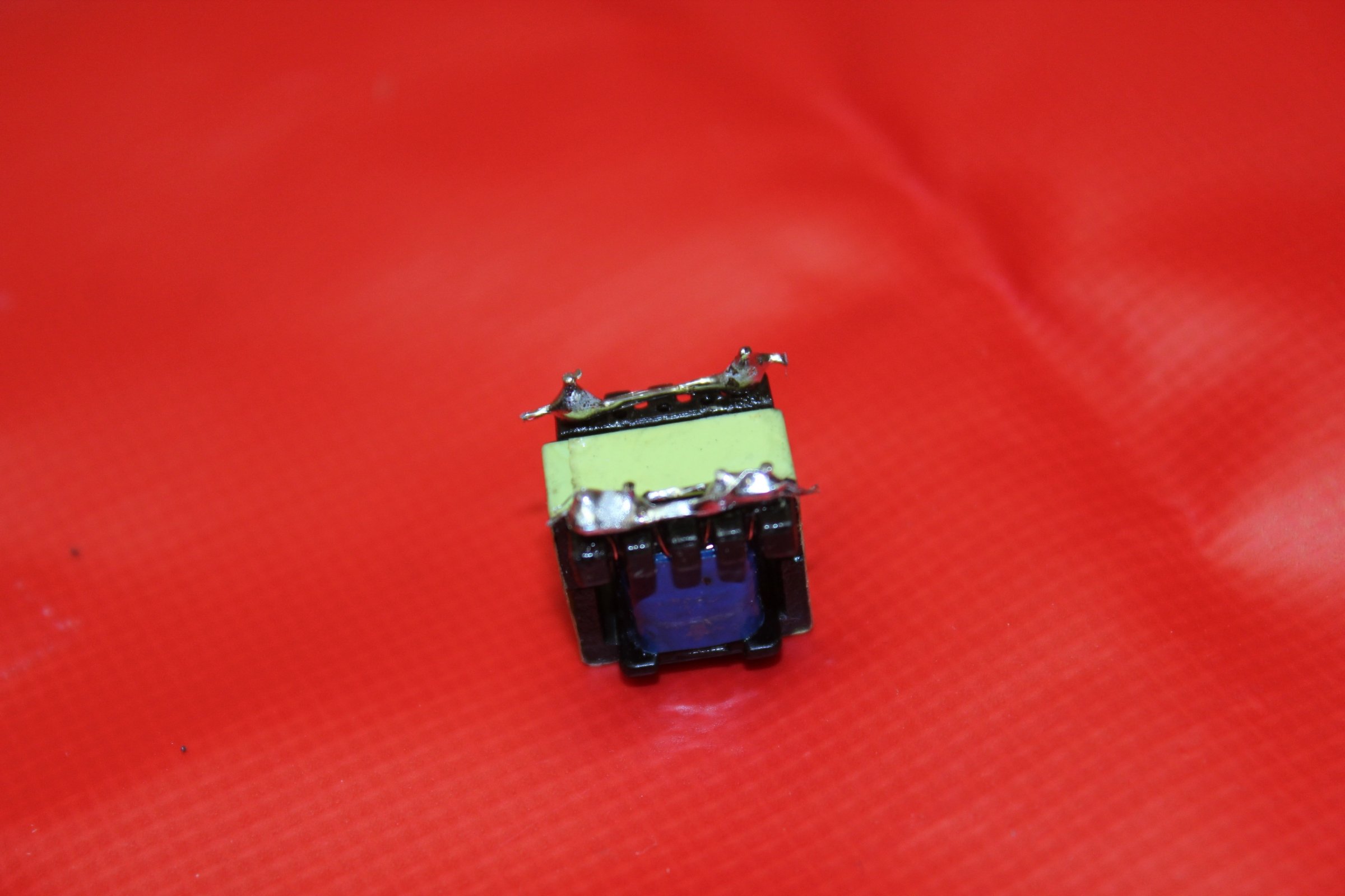
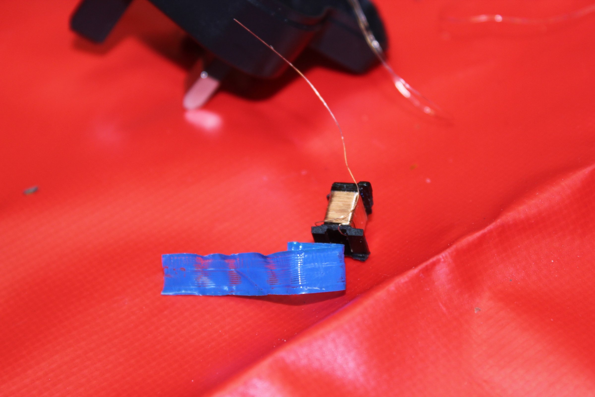
Transformer:
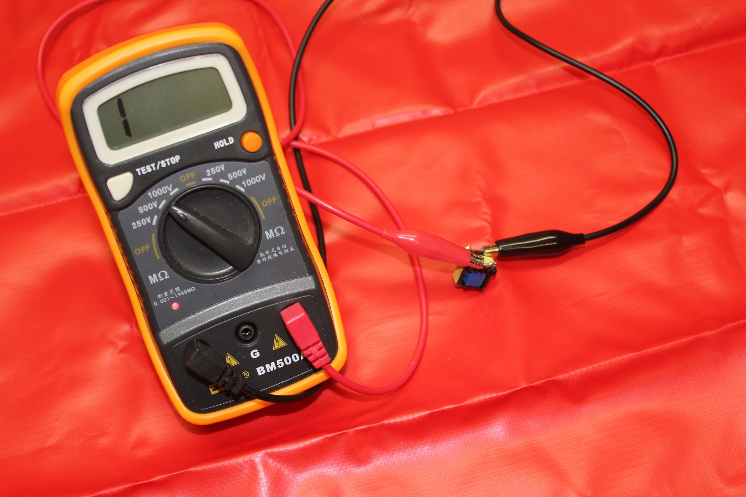
Here I performed a 500V DC Insulation Resistance test on the PCB mounted transformer (between primary and secondary side) as well as on the PCB between where the transformer normally goes, but got a reading of >2000MΩ both times! Where's the mains isolation issue?
500V IR test on Transformer:
500V IR test on PCB:
Poor quality separation material between windings:
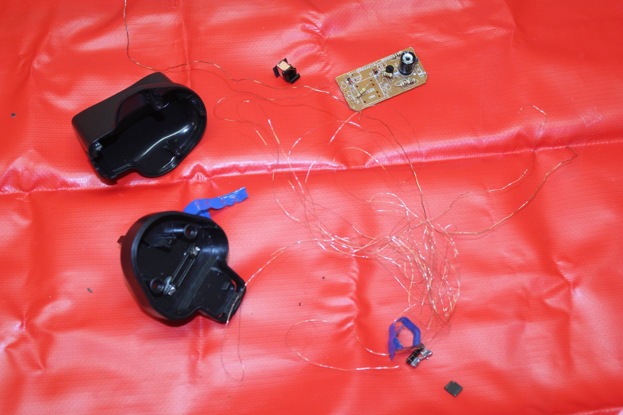
The Aftermath:
Summary:
One has to question that should it even be legal to supply such a poor quality power supply when supplied with a USB hub bought from a reputable on-line retailer like this one did.
In a nutshell, I can not work out if there truly was a issue between the mains input and the SELV output; the >2000MΩ reading on the 500V IR tests seems to be contradicting with the 33V AC that I got with my MM.
Also for those who have 6 minutes to kill, the video version of this thread is also available here on YouTube.
Regards: Elliott
the isolation between the mains primary side and the SELV secondary side was suspicious at best. Not only did my non contact voltage detection stick react to what should have been the separated isolated 5V output
, but when measured with a MM between mains earth and the 5v output jack, it displayed 33V AC. (Shown Below)Non-Contact stick reacting:
33V AC between Mains Earth (COM jack on MM) and the 5V output (VΩHz jack on MM):
So following the result I got from my MM, I decided investigate the workings of the switch mode power supply.
Moulded Casing:
Back view of PCB: (Notice the dry solder joints!)
Front view of PCB:
Circuit Layout:
Transformer:
Here I performed a 500V DC Insulation Resistance test on the PCB mounted transformer (between primary and secondary side) as well as on the PCB between where the transformer normally goes, but got a reading of >2000MΩ both times!
Where's the mains isolation issue? 500V IR test on Transformer:
500V IR test on PCB:
Poor quality separation material between windings:
The Aftermath:
Summary:
One has to question that should it even be legal to supply such a poor quality power supply when supplied with a USB hub bought from a reputable on-line retailer like this one did.
In a nutshell, I can not work out if there truly was a issue between the mains input and the SELV output; the >2000MΩ reading on the 500V IR tests seems to be contradicting with the 33V AC that I got with my MM.
Also for those who have 6 minutes to kill, the video version of this thread is also available here on YouTube.
Regards: Elliott
 A bit harsh may i say.