Question About Volt Drop

Right, you just need to remember that the first leg of the circuit carries the sum of all the currents, some current flows in the branch to the first socket so is subtracted from the total for the next leg, and so on. Just draw it out and the current in each conductor will be obvious.
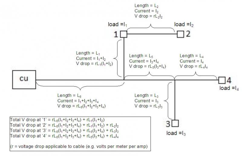
As you say, there nothing much more obvious than that (although I guess there was a time when people regarded it as less than obvious, since Mr Kirchoff felt in necessary to state his 'Law') - but that's not the point. As I've said repeatedly, if one knows the currents being drawn at each socket, then working out the voltage drop experienced at each socket is very trivial - which I presume is the point you're making.

The question we've been discussing is much more general than that. There is obviously an infinte number of ways in which loads/current can be distributed bewteen the sockets on a circuit within the limits imposed by the total available current ('design current' and/or In of OPD) and the maximum permissible load on each outlet. The question being asked is what is the maximum VD seen (at any socket) with any one of that infinite number of situations.

From the very start, my intuition (which maybe you would call 'the obvious') told me that (assuming same CSA cable throughout) the maximum possible VD will be seen, at the socket furthest from the CU, with loads arranged so that the furthest (in terms of total cable path length) socket draws the maximum permissible current for that outlet, the second-furthest draws as much as permitted of the available remainder, the third-furthest as much as possible of anything left ... etc.etc.

Maybe your mind is such that it is 'obvious' to you that my intuitive view is always correct. However, I have to say that when I initially tried to formally prove the general case ('convince myself') I found it less than obvious/trivial, particularly given that the 'general proof' has to encompass complex circuits with multi-level branching. I think I now have 'convinced myself', but do you really believe that the answer (in terms of an actual 'proof') is all that 'obvious'?
You don't actually need anybodies theorem, or any understanding of vectors quantities and imaginary numbers etc.
Essentially agreed. I've used nothing more than Kirchoff's Law (implicitly) and Ohm's Law - i.e. essentially looking at things 'from basic principles'. It was Eric who introduced the more esoteric mathematical concepts and discussions, which then flew off at a tangent!

If you want to make the exercise more challenging (and maybe even get some vector operators involved!) you could consider the situation in which the loads are each allowed to have any power factor :) [although I have a feeling in my bones that the answer {regarding max VD} will probably still be the same]

Kind Regards, John
 
Sponsored Links
I don't think you even need to use either of Kirchoff's laws, just Ohm's Law. Anything else is just academic willy-waving.

I don't feel the need to add anything to "make the exercise more challenging", since it was quite a simple question. If I could be bothered I'd have labelled each part of the circuit and then proveded an equation for the overal VD, but that wouldn't have helped the OP.
 
The currents, allbeit unknown are irrelevant to the question. I just wished to know the correct principle of working out the potential max volt drop liable to be present in the circuit, not know what the actual overall volt drop is as that would be impossible to know without knowing the current drawn at each 'leg'.
As has been said, the currents are not irrelevant. Without knowing the currents one cannot work out voltage drops, and therefore cannot determine the maximum possible voltage drop. You have to calculate the maximum possible voltage drop by knowing what all the currents are in the situation which gives the greatest voltage drop (once you have decided what that situation is).
So I assume whatever is plugged into any given socket on the diagram, I work out the volt drop for each load and add together to achieve the max volt drop for the circuit.
For a start, as you say, you do need to know the current resulting from each load - they are not 'irrelevant'. However, if I understand what you are saying, it's more complicated than that, because you have to consider how much cable is common to the paths to each of the sockets - you could only 'just add up' the individual voltage drops if the entire cable path was identical for all loads (e.g. if all were plugged into the same double- or triple-socket). At the other extreme, if the circuit were such that there was no cable common to the various loads (i.e. a 'star' circuit arrangement, with each branch radiating from the origin), then the maximum VD would be the greatest seen at any one of them, not the total of them all.

Kind Regards, John.
 
I don't think you even need to use either of Kirchoff's laws, just Ohm's Law. Anything else is just academic willy-waving.
One cannot avoid using Kirchoff's First Law, even if one calls it 'obvious' (to us, now), rather than giving Mr Kirchoff credit. When you wrote:
....the first leg of the circuit carries the sum of all the currents, some current flows in the branch to the first socket so is subtracted from the total for the next leg, and so on.
... you were merely paraphrasing (in context) that Law, weren't you?
If I could be bothered I'd have labelled each part of the circuit and then proveded an equation for the overal VD, but that wouldn't have helped the OP.
Any of us could have done that, for given loads (or even for loads represented by algebraic symbols). However, that's different from answering the OP's question which, as I understand it, is how to determine the maximum possible (numerical) VD in a (any) radial circuit

Kind Regards, John
 
Sponsored Links
No, I wasn't paraphrasing from Kirchoff, and I see no reason why his laws were even mentioned.

I do know that many of the posters here could also have reduced the answer to a single algebraic equation (probably better than I could), but as I understood the OP he only wanted to know the principle of how to calculate the voltage drop in his simple circuit. He didn't ask for the principles of calculation voltage drop in more complex circuits, or with complex loads.
 
No, I wasn't paraphrasing from Kirchoff, and I see no reason why his laws were even mentioned.
With respect, I don't think that I ever mentioned any Laws or Theorums, until you recently raised the issue of "anybodies theorems". However, there is no doubt that, whether you call it paraphrasing or not, you are applying the principle which is formalised in K's First Law. Anyway, that's not the point.

I do know that many of the posters here could also have reduced the answer to a single algebraic equation (probably better than I could), but as I understood the OP he only wanted to know the principle of how to calculate the voltage drop in his simple circuit. He didn't ask for the principles of calculation voltage drop in more complex circuits, or with complex loads.
We obviously made differing interpretations. Given the reference to the regs, I assumed that the OP was interested in the principles to be applied in order to determine the maximum possible VD in a (any) branching radial circuit and that interpretation seems (to me) to have been confirmed by his/her (I'm not sure about your assumption that 'KayBull' is male!) recent post, in which (s)he wrote "I just wished to know the correct principle of working out the potential max volt drop liable to be present in the circuit". I know it says 'the circuit', but I presume that his/her interest are general.

Kind Regards, John
 
...I just wished to know the correct principle of working out the potential max volt drop liable to be present in the circuit, not know what the actual overall volt drop is as that would be impossible to know without knowing the current drawn at each 'leg'.
OK. Further to my recent post, please see the diagram below, which relates to the example circuit you originally posted.

I have called the currents drawn by each of your four circuits I1, I2, I3 and I4, and the lengths of the various segments as L1-L6, as indicated on the diagram. What you have to do is to work out the current in each of those cable segments, then multiply that by the length of the segment and the appropriate figure for resistance of the cable (which I've called 'r' - e.g. 18 mV per amp per metre for 2.5mm² T+E cable) to get the voltage drop in that segment. Having done that for all of the segments, then, for each socket, you add up the voltage drop in each of the segments which form part of the path between that socket and the CU to get the VD at that socket. Having done that for each socket, you can look to see which is the maximum. All of that obviously requires that you know the currents being drawn at each socket (and lengths of the circuit segments).


If it's the maximum possible VD at any socket which interests you, then you obviously have to decide what arrangement of currents will result in the maximum possible VD being seen at one of the sockets. For a simple circuit like yours, I think the maximum VD will occur (at the socket with the longest path), when the socket with the longest cable path back to the CU (which, depending on the layout, could be any of yours other than socket 1) is carrying the maximum permitted current, and the remainder of the 'available current' is drawn via the socket with the next-longest path. If it were a 20A radial (i.e. 20A MCB in CU) and the sockets were all single, then that would arise when 13A was being drawn from the furthest socket and 7A from the next-furthest one.

Does that help?

Kind Regards, John
 
JohnW2 that diagram is EXACTLY what I have been looking for! Makes it all much clearer to fully understand rather than trying to follow written instructions. Really sorry that I was unable to reply sooner. I really think there should be a sticky regarding volt drop and the principles involved in order to calculate it in simple and complex circuits. IMO one doesn't need to involve the flow of current unil they understand the method of calculating each 'leg' in the circuit concerned.

All I wish to do now is experiment with different amperage which will consist of made-up figures and I will apply those to some sockets to achieve the volt drop for each cable leg. I presume then once I have gained the volt drops for each cable leg, I tot them all up and if they exceed 11.5V (5% max permitted voltage on a 230V in supply installation for power circuits), I can apply methods such as changing the size of conductors/ lengths etc to decrease the total volt drop in order to meet volt drop requirements. This will be a great exercise for me to gain familiarity of the calculations involved. Many thanks again for that diagram :D
 
JohnW2 that diagram is EXACTLY what I have been looking for! Makes it all much clearer to fully understand rather than trying to follow written instructions. Really sorry that I was unable to reply sooner. I really think there should be a sticky regarding volt drop and the principles involved in order to calculate it in simple and complex circuits.
You're welcome, and I glad yoiu found it helpful.
IMO one doesn't need to involve the flow of current unil they understand the method of calculating each 'leg' in the circuit concerned.
One certainly has to first understand the underlying concepts/methods. However, your question appeared to be about the 'maximum possible voltage drop in the circuit' (which, depending upon the situation, could arise at any socket**) - and you obviously do need to know both the currents and the 'leg lengths' to be able to work that out.
[** the maximum VD could only arise at socket #1, jointly with #2, if there was zero load at socket #2]
All I wish to do now is experiment with different amperage which will consist of made-up figures and I will apply those to some sockets to achieve the volt drop for each cable leg. I presume then once I have gained the volt drops for each cable leg, I tot them all up and if they exceed 11.5V (5% max permitted voltage on a 230V in supply installation for power circuits), I can apply methods such as changing the size of conductors/ lengths etc to decrease the total volt drop in order to meet volt drop requirements. This will be a great exercise for me to gain familiarity of the calculations involved. Many thanks again for that diagram :D
Indeed. In this day and age, the nicest way to do that would be to set up a spreadsheet that would allow you to specify each of the currents, each of the leg lengths and each of conductor sizes - then you could play with all those factors to your heart's content and instantly see what effect the changes have on all the voltage drops (and the maximum). If you want to try that, and want any help with it, just let me know.

Kind Regards, John
 

DIYnot Local

Staff member

If you need to find a tradesperson to get your job done, please try our local search below, or if you are doing it yourself you can find suppliers local to you.

Select the supplier or trade you require, enter your location to begin your search.


Are you a trade or supplier? You can create your listing free at DIYnot Local

 
Sponsored Links
Back
Top