In case I am going barking mad.
Take a circuit rated at 70amps per phase, three phase and neutral.
5% volt drop max (of 230v as neutral required).
What volt drop figure do you get for a circuit running 150m run in 25mm?
I calculate it to be 15.75 volt, using 1.5mV/a/m
1.5 x 70 x 150
-----------------
1000
This is what I would expect.
With my very old amtech calc software, this agrees.
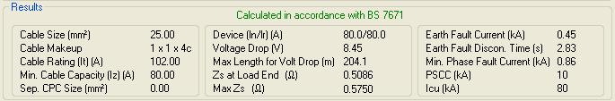
With the new amtech calc software from last year, I get this:
Take a circuit rated at 70amps per phase, three phase and neutral.
5% volt drop max (of 230v as neutral required).
What volt drop figure do you get for a circuit running 150m run in 25mm?
I calculate it to be 15.75 volt, using 1.5mV/a/m
1.5 x 70 x 150
-----------------
1000
This is what I would expect.
With my very old amtech calc software, this agrees.
With the new amtech calc software from last year, I get this: