Reading to expect with clamp on multi meter?

Joined
27 Jan 2008
Messages
23,519
Reaction score
2,642
Location
Llanfair Caereinion, Nr Welshpool
Country
United Kingdom
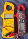
I have had a clamp on multi meter for years, but only one decimal point and only AC. 1663423977553.png So at long last I have a meter to measure mA and DC. So testing measured the charge rate on battery charger, and combined neutral and line incomers and DC at incomer.
Leakage seems between 18 mA and 21 mA but this is all 14 RCBO's so seems OK, and DC component shows as around 10 mA higher than expected. Battery charger was as expected so readings seem to be within what is expected, but other than leakage normally less than 30 mA as above that would trip a RCD in a home with only two, I have never before actually measured it.

I did find on DC range important to select range and press zero first, but with meters I have used in the past one started to get a knowledge of what to expect, so when you saw 1M Ω even if a pass, you know that is rather low, and one looks at why, same doing earth rods, expect a single rod around 60 Ω so if you read 2 Ω one looks for a water or gas pipe not disconnected for the test.

So want to know what is a normal reading, I would have said over 9 mA leakage the supply needs splitting into multi RCD's but only test in past was if the RCD tester tripped at ½ rated current I assumed some thing wrong.
 
Sponsored Links
I did find on DC range important to select range and press zero first,
Yes, and you must hold it near the wires to be clamped in the orientation it is going to be used and not rotate it after zeroing.

I have one the same but have only used it for the car. It is easy to find (if there are any) parasitic drains.

So want to know what is a normal reading, I would have said over 9 mA leakage the supply needs splitting into multi RCD's
Ideally perhaps but I don't really see why. If the RCD doesn't trip then all is well.

I don't know if there is a normal - as in applicable to everyone. It depends what equipment there is.
 
.... at long last I have a meter to measure mA and DC. .... Leakage seems between 18 mA and 21 mA but this is all 14 RCBO's so seems OK, and DC component shows as around 10 mA higher than expected.
I've only ever used such things to measure currents which were essentially 'pure AC' or 'pure DC'. Does the spec/documentation of yours say anything about the accuracy of (either) reading when both AC and DC components are present - i.e. does the presence of a DC component affect the accuracy of displayed AC current, or the presence of an AC component affect the accuracy of displayed DC current?

I personally rarely find it easy/convenient to use these things, other on single-phase 'tails', since its often difficult to put them around L & N (say of a circuit, or even an individual load) without also having a CPC in the equation.

Kind Regards, John
 
Last edited:
I have not fully read the instructions, however I did note on battery charger no reading until DC selected, and it defaults to AC so move the range change and you go to AC on the current ranges, not really bothered reading voltage or ohms or frequency yet I have had a meter which could measure them for years, as seen on left of picture.

It will just about take the two singles for total house supply, so can now read down to 1 mA earth leakage, it is a large house, three floors, but I had not expected such a high reading, since spread over 14 RCBO's not a problem, but not what I expected.

Noted what @EFLImpudence has said about zeroing the meter first, there was no zero button on the old meter, it did have a hold button, on the side, but bought the old one when working in Hong Kong before the take over, so now 25 years old, not as old as the AVO Mk8 which was got in 1980, but still getting on.

For anything with a plug I have plug in energy monitors, and the reading for battery charging input to charger and output from charger match so new meter seems accurate enough for my use. For DC non disconnect in the past used these
1663482989411.png
which are not very accurate. Also had larger version for starters, more an indentation of current use. My version was 60-0-60 amp. Below an amp had to use meter in series.

I am very wary if any RF around, I had the AVO auto electricians meter in the Falklands, and measuring two way radio current and it showed 80 amp but cable did not melt, and this was not a clamp on, had to borrow a Fluke meter, the auto electricians meter had a low ohms per volt so that stray voltages not recorded, but the old meter
1663483679053.png
was the best, it allowed measuring volts and amps at the same time, however not much good to check an alternator when voltage is 13.2 to 14.8 needed a suppressed zero meter or digital. And -10-0-100 amp scale not the best option.

But having been trained with these moving to a clamp on with hall effect is some thing new for me, and I don't know what to expect.
 
Sponsored Links
I have not fully read the instructions, however I did note on battery charger no reading until DC selected, and it defaults to AC so move the range change and you go to AC on the current ranges, not really bothered reading voltage or ohms or frequency yet ...
As I said, I don't know (probably have very rarely tried with mixed AC+DC).

I would not expect a 'clamp' AC current reading to be affected by a DC component (unless, perhaps, it were 'massive'). However, I don't know enough about Hall Effect devices to know how they behave in the presence of an AC component - so I would certainly not trust measurements of a DC current in the presence of an AC component unless/until I was reassured by documentation (and/or experiment!) that the DC measurements were fairly accurate in that situation.

Although utterly different, with a conventional ('2-pole') DVM, when measuring voltage one certainly gets some 'issues' as regards AC and DC. I've just tried ... with a 9V battery, my meter displays 8.9V on the 20V DC range and 19.8V on the 20V AC range! With 'mains', it displays about 245V on the 600V AC range, and about 6V on DC ranges.

Kind Regards, John
 
Only one firm I have worked for, GEC large steam turbines, has ever calibrated standard multi-meters, they also calibrated crimp pliers. I have like I am sure many others compared instruments, so it would require multi instruments to go faulty for false reading to be taken over a length of time.

This did happen once for me, with a PAT tester, it was found still in the box unused since bought, so was sent away to be calibrated before being used, as likely 10 years or more old, even if in new condition.

I asked for and got software to record the results, and it required the readings entering, but the tester was a simple go/no go light to show if pass or fail, I queried this, and felt daft when the suppler say enter the figure on the calibration certificate.

However the certificate did not have the pass figure on it, so I asked for a new certificate with this figure entered on it, it was a traceable record so should be no problem. Well it was, the tester had been made at a time when the pass mark was lower, and was passing items which should have possibly failed, so I was left with 6 months worth of useless PAT testing records. So much for calibration houses and traceable records.

After that I used some method to test my own meters, be it testing the same outlet at home, or testing a known resistor, if a loop impedance tester fails it's yearly test, then you have a years worth of useless test results, so one wants to be alerted week by week, so test the same outlet before taking the meter out, so you know straight away if meter faulty. And if the firm has two or more meters, the chance of them all being out by the same amount is very slim.

So new meter was tested against old meter with same results, but as you say the DC current is some thing new, in the past always had to part the conductors and put the meter in series, in the main I used the near enough reading from the hold on meter,
1663576367479.png
which was enough to see if the dynamo was charging, but to set charge rate needed the whole box of tricks, as the alternator replaced the dynamo the need to set charge rate in the main went, only the CAV AC203 alternator had charge current control using the special regulator with the M1 and M2 terminals connected across a steel shunt resistor. Showing my age. Only ever found them fitted to buses, idea was to maintain battery when bus ticking over with all interior lights on. I hatted those alternators, they were darn heavy, not as heavy as the dynamo with bucking coils they replaced, but still heavy.

But one gains knowledge over the years of what to expect, even if 1.38Ω is a pass, if you see that reading 2 meters from the CU it rings alarm bells.

So at what earth leakage current should those bells ring? I know 9 mA is considered max permitted before you split circuits so using another RCD, but I am sure that is not exceeded with any of the RCBO's there are 14 of them, but collectivity seeing 18 to 21 mA is that normal for the whole house?

At one point I did have a leaking roof, which did take out on RCBO, and by switching them off or on one at a time I could test the individual circuits without opening the consumer unit, or take the cover off, but out of pure interest only don't really want to have to reset all the clocks in the house etc. So just wondered what is normal.
 
I know 9 mA is considered max permitted before you split circuits so using another RCD ...
That might be fair enough when the loads protected by one residual current device are all hard-wired but, as I always say, I think that is a pretty ridiculous idea when sockets circuit(s) are involved (which is usually the case when we are talking about 'leakage'), since one has absolutely no knowledge of what loads (with what leakages) may be plugged into the sockets.

Kind Regards, John
 
So at long last I have a meter to measure mA and DC. So testing measured the charge rate on battery charger, and combined neutral and line incomers and DC at incomer. .... Leakage seems between 18 mA and 21 mA but this is all 14 RCBO's so seems OK, and DC component shows as around 10 mA higher than expected.
What is the make/model of your meter?

Following my earlier comments, I had a look around to see what the documentation of 'mA clamp meters' (often described as 'leakage meters/testers') had to say about the accuracy of low DC current measurements in the presence of AC components. However, (albeit perhaps because I am incompetent at searching!) not only have I not yet managed to find that, but I haven't actually yet found a clamp meter (even very expensive ones) which claims to be able to measure very small (handfuls of mA) DC currents at all, let alone in the presence of AC components! Am I missing lots of things?

Kind Regards, John
 
This is the advert the manual I have found here it was the cheapest one I could find, so likely not that accurate. But far better than what it replaces.
Thanks. That one certainly seems to claim to have 1 mA resolution for DC (clamp) current measurement (presumably "down to 1 mA"?) - which, as I said, was something I had not found in my searching. However, it says nothing which addresses the question I asked - i.e. how the measurement of very small DC currents may be affected by concurrent AC components in the current.

It seems a very reasonable (perhaps 'too low'?) price, so I might even get one and 'do some experiments' in order to get some sort of answer to my question!

Kind Regards, John
 
This is the advert the manual I have found here it was the cheapest one I could find, so likely not that accurate. But far better than what it replaces.
I've been reading some of the reviews of this meter.

Most seem to say that it is pretty good (particularly for the price), but those who have taken them apart have identified some potential construction issues.

Some say that current readings below 10 mA cannot be taken too seriously (one suggested that the displayed readings seem to be 'random'!!). However, one thing on which most seem agreed is that when measuring small DC currents, it is exceptionally susceptible to any stray electromagnetic fields (which can result in very inaccurate readings), so that it is absolutely crucial, when measuring DC current, to use the 'zero' facility (multiple times if necessary) before attempting to take a measurement, and ideally with that 'zeroing' happening with the meter's jaws in exactly the same place that they will be for the subsequent measurement.

Kind Regards, John
 

DIYnot Local

Staff member

If you need to find a tradesperson to get your job done, please try our local search below, or if you are doing it yourself you can find suppliers local to you.

Select the supplier or trade you require, enter your location to begin your search.


Are you a trade or supplier? You can create your listing free at DIYnot Local

 
Sponsored Links
Back
Top