Replace analog timer?

I have a problem with central heating, nothing to do with the system, it is down to me. Winter I consider 22ºC to be nice, and Summer 22ºC is too hot, but in general the TRV heads control room temperature, and when the room is heated, so not really sure why I need a wall thermostat or programmer. They are really a throwback from a by-gone age.

But not all my TRV heads are linked to the hub that controls the boiler, but the point is, as it is now, not perfect, but near enough, so we work with near enough engineering, and if near enough, then leave it alone.
 
Many others disagree.
Yes I will agree, I did not understand how storage radiators were ever classed as central heating. There were systems with a central heat store and fans to direct heat to rooms as and when required, but most had no central control at all.

It does seem that as soon as central heating started to be fitted into homes, we tried to decentralise the control.

Size matters, a two up two down, would have just lower room control, and enough heat came through the floor for bedrooms, but as the size grows, we find bedrooms used as offices, studies, rooms to do homework in, and I never really got my head around living room and best room.

However, my own home, 14 heated areas, if I heated all 14 24/7 it would cost a fortune, so rooms are heated as and when required, but having one boiler means only one room needs a flue, OK we also have an open fire, but is does make the building on the house cheaper and simpler if only one boiler serves the whole house.

But control wise, we can group rooms, with some being heated 24/7 like the bathroom, some overnight like the bedrooms, and some day and evening like living room, and some just when required, like an office, craft room, etc.

Once the house has rooms only used on some days, or some hours in the day, we still want a central heat generator, but the control needs to be spread around the house.

How we control will vary, as a couple, as a family with small children, changing as the children grow up, returning to two again in latter years, so the central heating has to be designed so it can also vary as the family grows.

So in the main, the old motorised valve is out, as it is too inflexible, the new motorised valve or TRV as we now call them, can have heads swapped and reprogrammed to suit our changing needs. There will be the exception, where the granny flat is all either heated or not heated, but in the main, we look for a system which can change with our needs, and the TRV with interchangeable heads, seems to best allow for changing needs.

So we may have three bedrooms and only one has a linked TRV head, there is often no need for every room TRV head to be linked, and where radiators are against a cold wall, it may be better to have a wall mounted sensor, and it may be an advantage if that sensor has local controls (i.e. a wall thermostat) and it may work out better if so many controls are grouped together as zones.

But the idea of every room having its own hub linked temperature control or the opposite where every room just has a proportion of a control rooms requirements, does not really work, we have to select some happy balance between the two.

This balance may well be just using the TRV to stop rooms overheating, but even though I know the theory, when my mothers room got too hot, I blamed the wall thermostat, which of course is nonsense, as both the wall thermostat and the TRV both need to be faulty for a room to overheat.

I quickly realised my error, and went to set the TRV, so want the room at around 21ºC to 22ºC and I look at the TRV head, and it says *123456, who in their right mind, labels a thermostat *123456?

Well it seems the TRV at setting 2.5 will be fully open at 17ºC and fully closed at 21ºC so 5ºC between fully open and fully closed, so to have a room at 20ºC it will depend on outside temperature, radiator size, room size and the setting of the lock shield valve, as to what number it needs setting at.

Even with an electronic TRV head, it may mean fully open and fully closed only has a 0.5ºC variation, but to exercise the valve, which happens every Saturday at noon, we hear the motor running for 5 minutes, that how slow the valve is, so with no lock shield valve, the radiator would be stinking hot before the valve can close, so we need to set the lock shield valve.

Mother house, found every lock shield valve wide open, should have be set by installers, but they didn't. And I could not find my differential thermometer to set them with. But once electronic heads were fitted, I had a display 4 TRVs-1.jpgso clearly the current should not exceed target, so if it did, the lock shield needs closing a little. Once set it worked spot on, but it took some time to gradually trim in each room. More than 4 rooms, but once the lock shield set, the old mechanical TRV heads worked fine.
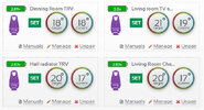
So confident I now knew how to set up the lock shield, moved to new house, but this had an on/off boiler, not a modulating boiler, and it did not quite work out the same. So yes the method does not work with all. There seems to be an exception to every rule.

I now realise why to become an engineer, we are looking at degree standard, and heating and ventilation engineers do earn their pay.

But in the main we are not looking for temperature control to within 0.5ºC of what is set, we work with near enough engineering, the easy method is something like Drayton Wiser TRV heads on every radiator and let them call for heat when required, but the heating engineer can reduce that, and only fit linked TRV heads to some radiators.

But as the homeowner we have to decide how much we are willing to pay, I have just 4 linked thermostats, even with 14 radiators, and I find that near enough. I will not claim perfect, it's not, but it is near enough.

 
Well I have been upfront with a few electricians about what I have and what I want, and none want to touch it. :unsure:
I have looked a little bit further, by taking the cover off the old programmer and can see that no wires go to L2 as far as coming into the programmer. That was the line that I had to isolate and shield, if one did.
I am trying to see if I can remove the plate where all the connectors are to get a clearer picture of the wiring.

One thing we mentioned today over breakfast was... if the power goes out (which it does now, as I have it on a smart switch for 23 hours a day), the pilot light is still lit. With the programmer on constant and the smart switch coming on, the boiler fires up. I am on HW only at the moment.

So what did they have back in 1980 to shut off the gas, when safety was compromised?

Edit: Never mind, I managed to find this?
Flame Safeguard: Uses an ionization electrode to detect the burner flame and shut off the gas valve if the flame goes out. [1, 2]
 
Last edited:
Well I have been upfront with a few electricians about what I have and what I want, and none want to touch it. :unsure:
Oh, that is a bit of a surprise. Mind you, when I tried to get my central heating sorted, the plumber and heating guy both said they did not understand my electrics. Lucky I did.

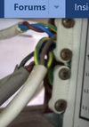
So I look here 1785005109625.png and I see 4 cables, so a good start is to work out what each cable does.

The way I sorted mine was to work out what cables went where, and then work out how I could use the existing cables to re-wire the system.

So 4 cables, likely one is the feed, one goes to boiler, and one goes to the pump, but it could be to a thermostat, either CH or DHW or both, or a motorised valve, you may have told me, but since 19th June can't remember, and today is not a good day, I am in pain.

Seem to remember C Plan, but if you can refresh my memory please, so all is on one page, and I am not flitting between three pages to renew my memory as to what you have.
 
I know the feeling. :( My memory is shot these days.

Yes, I have 4 wires.
1 is the power from a 3 pin mains socket.
2 is power to the pump on the wall adjacent to the boiler.
3 is a lead that goes to what I thought was the igniter, but now not so sure. Will take a pic tomorrow.
4 I believe is the thermostat. I am assuming that as it comes from the existing trunking on the wall behind the boiler.
The thermostat lead is gray, all others are white, and is quite hard, compared to the other leads.
I have since marked the white leads with tape, so will try and take better pic and detail which is which.
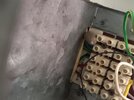
Also a pic from within the programmer.

Asking Gemini, it seemed to think, that the thermostat would be powered from the boiler, and it's return line would actually switch on the HW&CH when the thermostat made the connection.

I am trying to take more pictures, for my benefit, but the thermostat lead is restricting the movement of the programmer to a fair degree.
 
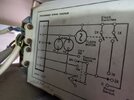
Ok, I think, now looking at this picture, I am in a pretty good place?
All I need to do is wire the new programmer exactly like this picture.
 

Attachments

  • Boiler Wiring.jpg
    Boiler Wiring.jpg
    32.1 KB · Views: 5
  • 20260726_081202.jpg
    20260726_081202.jpg
    380.8 KB · Views: 5
OK slowly working it out, I will assume for moment C Plan basic,
C-Plan_old2.jpg

In the main still had a wiring centre, but it would seem not in your case, so looking at that plan, one would expect 4 cables, the time controller has to power the boiler when both central heating and domestic hot water is required. There were little switches on the old timers to allow it to be configured this way, and a mechanical latch so you could not select just central heating.

This returns me to earlier posts, where I talked about would you ever want DHW on its own? In winter, it may as well heat DHW when doing the central heating, but to use it for DHW in summer, is likely not an economic prospect, and using an immersion heater would be better.

I am an electrician not a plumber, so there may still be some old timers around which I don't know of, but I have not seen one in years, so it would be easier to do away with the DHW only, and you can do away with the timer all together and use a programmable thermostat instead.

But need conformation there is no motorised valve, or tank thermostat, need to be sure it is a basic C plan before we try and work out how to replace the timer with a wiring centre and the thermostat with a programmable one.
 
I think I have already stated that gas is still cheaper for me for HW only. I am happy to keep it as it has always been, HW only or HW&CH.
I do not have any motorised valves, nor a tank thermostat? The temp of the water is controlled by a white knob with values 1 to 6 (or so I believe).
I believe that is if I wire exactly as I have now. That brown wire in L3 to 3, and red wire in L1 to 4, and the earths and neutrals as they are now, then we should be good to go?
As the new backplate is a lot smaller that the original, I plan to wire the common wires into Wago connectors and take a single wire from them to the terminal contact on the backplate?

However I am not an electrician, hence checking here, but does this sound feasible to you?
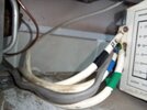
Black is the mains wire
Blue goes to what I thought was the igniter, but now think it is the gas valve, where that white knob is.
Green goes to the pump
Grey wire I am assuming is the thermostat, as it comes from trunking on the wall behind the boiler.

Edit: At the moment I have it on HW only and Constant, and the boiler comes on for 1 hour per day via a smart switch.
 

Attachments

  • 20260726_085223.jpg
    20260726_085223.jpg
    194.8 KB · Views: 1
Last edited:
The original Hive thermostat, can be configured to work as you want, it was a software configuration it has two relays inside, and configured for gravity think they call it, one relay controls pump, and one controls boiler.

One can also use Nest Gen 3
C-Plan_basic_Nest.jpg

Because you have access to com terminal, you can take the feed out of the com, as shown to the boiler, but many programmers and thermostats or programmable thermostats on the market today will not work with C Plan. Some of the Nest thermostats have been made into bricks because google removed support, so I would not recommend Nest. But think some of the Tado units are the same, but can't be sure.

I am using Nest Gen 3 with C Plan, it is to me a useless thermostat as it will not connect to TRV heads, but keep it connected in parallel with Wiser, so if my immersion fails, I can use oil for DHW.

Careful with Nest, the USA versions are very different to the UK ones.
 
I am planning on using that Siemens RWB29si programmer.
I already have that fitted to a backplate and another plate to be able to bolt to the boiler. So the physical side of things is completed.
Just the electric side of things to do.
Looking at the picture of the connector blocks, they lettering also shows which is which.
So I am pretty happy, I know what goes where now.

Thank you for your input, all of you.
 

If you need to find a tradesperson to get your job done, please try our local search below, or if you are doing it yourself you can find suppliers local to you.

Select the supplier or trade you require, enter your location to begin your search.


Are you a trade or supplier? You can create your listing free at DIYnot Local

 
Back
Top