Replacing Danfoss RMT230 with a Danfoss TP5000Si

Joined
16 Nov 2009
Messages
21
Reaction score
0
Location
Manchester
Country
United Kingdom
By examining the outside of the current thermostat (not been inside yet - will do tomorrow), I believe I have a RMT230.

How can I tell if I need to replace my current stat with a battery powered or mains powered version of the TP5000Si ?

Thanks :?:
 
Sponsored Links
How can I tell if I need to replace my current stat with a battery powered or mains powered version of the TP5000Si ?
It depends on how many wires connect to the existing stat.

If there are only two, you must use the battery version; if there are three, you can use either battery or mains.

This is because the third wire is a neutral and the mains version will need this to run the clock and electronics. Battery versions use the battery(!) to do this. The other two wires are Live (from timer) and Switched Live to boiler.
 
Thanks for this.

Didn't manage to get the time to go inside the current stat today - will do it during the week.

But, from what you say, the battery version would be the safe bet (ie would work with either 2 or 3 wires) whilst the mains version has the obvious advantage of not needing battery replacement. Are there any other obvious pros/cons I've not mentioned ? :?:
 
Sponsored Links
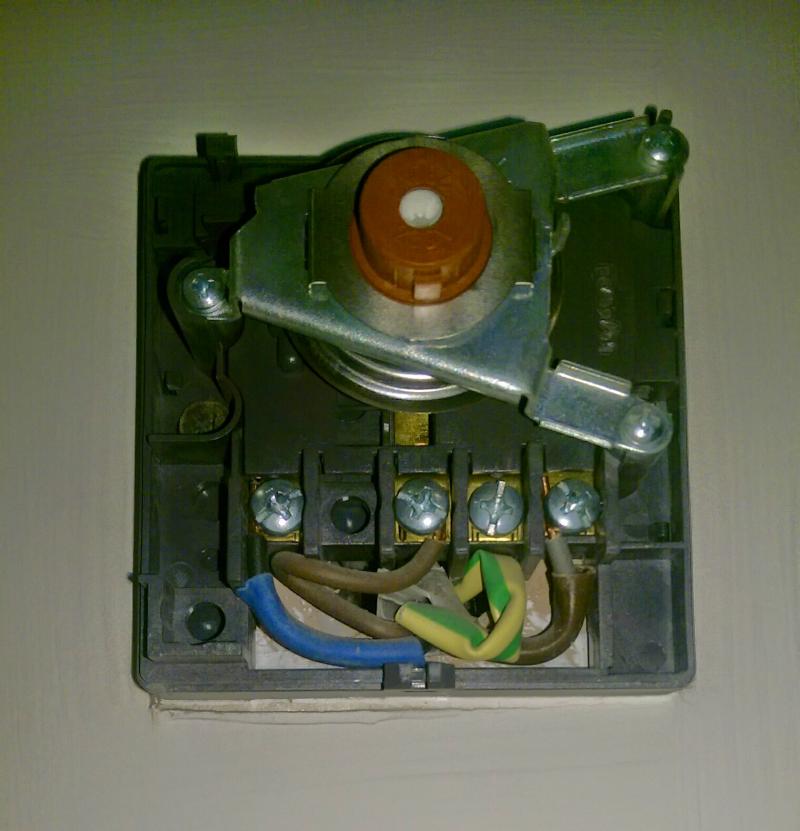
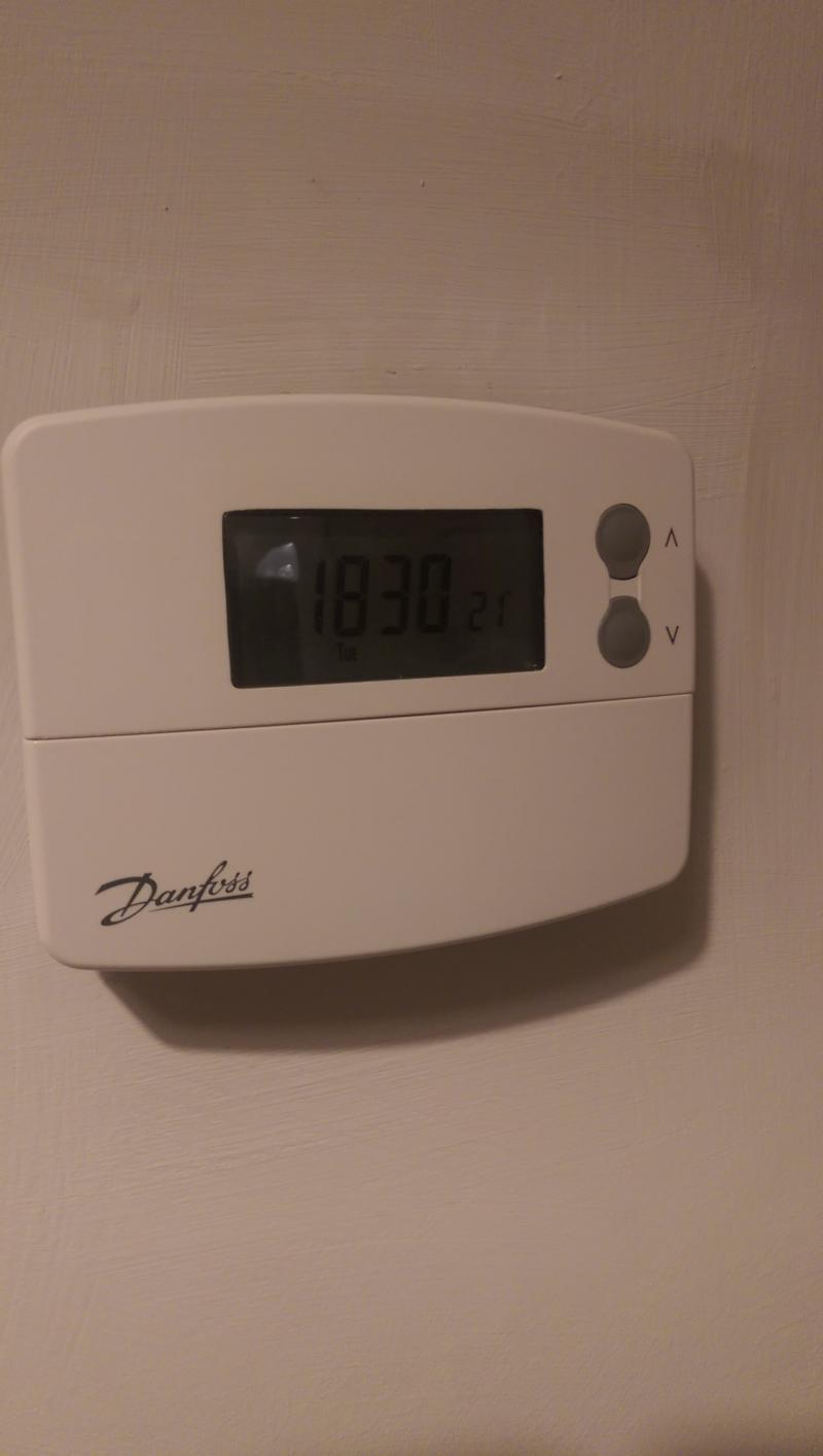
I've now been able to go inside my current stat and have confirmed that it is indeed a Danfoss RMT230 (with parallel accelerator) and is fitted to a metal back box.

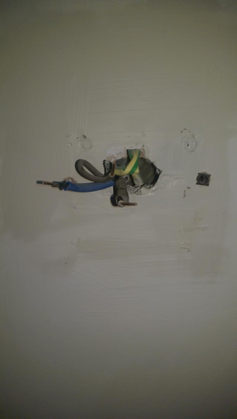
The cable is 3-core-and-earth with old colours : Red, Blue, Yellow and "Bare".

Connections are currently wired as follows :

Red (presumably "Live") → Terminal 1 (COM)
Yellow (presumably "Switched Live") → Terminal 2 (ON)
Blue (presumably "Neutral") → Terminal 4 (N)
Earth → Back Box

I've been looking at the wiring diagrams for the Danfoss TP5000Si (battery powered) and TP5000MSi (mains powered) versions and believe they are wired as follows :


1) Battery Powered

Red → Terminal 2 (COM)
Yellow → Terminal 3 (NO/ON)
Earth → Back Box (as before)
Blue → Unused and 'taped-up'


2) Mains Powered

Red → Heating Terminal 2 (COM)
Yellow → Heating Terminal 3 (NO/ON)

Blue → Electronics Terminal B (N)
Earth → Back Box → Electronics Terminal Earth

+ Short piece of Red wire connecting Heating Terminal 2 (COM) and Electronics Terminal C (L)


My main question is : Are my wiring details above correct ? Have I got them right ?

Also : Any advice re the choice of battery powered or mains powere ?

Many Thanks
:?:
 
Connections are currently wired as follows :

Red (presumably "Live") → Terminal 1 (COM)
Yellow (presumably "Switched Live") → Terminal 2 (ON)
Blue (presumably "Neutral") → Terminal 4 (N)
Earth → Back Box
Sounds right. You can always check the red and yellow with a meter, if you have one.

1) Battery Powered

Red → Terminal 2 (COM)
Yellow → Terminal 3 (NO/ON)
Earth → Back Box (as before)
Blue → Unused and 'taped-up'
Correct

2) Mains Powered

Red → Heating Terminal 2 (COM)
Yellow → Heating Terminal 3 (NO/ON)

Blue → Electronics Terminal B (N)
Earth → Back Box → Electronics Terminal Earth
+ Short piece of Red wire connecting Heating Terminal 2 (COM) and Electronics Terminal C (L)
It's OK, but better to connect the Red to Terminal C/L

The Live supply probably comes from the CH ON terminal of your existing timer/programmer. You can either set this to constant or, preferably, move the wire to the L terminal of the timer.

As for which to use - battery or mains - it's really up to you. Mains means no batteries to buy (every 2-3 years). Battery means that you don't lose any settings if the power fails.
 
Thanks again for your comments.

Just to be 100% clear, you would prefer wiring for the TP5000MSi to be as follows :


2) Mains Powered

Yellow → Heating Terminal 3 (NO/ON)

Red → Electronics Terminal C (L)
Blue → Electronics Terminal B (N)
Earth → Back Box → Electronics Terminal Earth

+ Short piece of Red wire connecting Heating Terminal 2 (COM) and Electronics Terminal C (L)


Am I understanding you correctly ?


In terms of the Battery Powered v Mains powered choice, the Instructions for both versions say that settings are held in a non-volatile memory chip (and hence effectively permanently held).

The deciding factor might be price - it looks like I can find the Battery version at £45 whilst the cheapest Mains version seems to be £65 !!
 
Just to be 100% clear, you would prefer wiring for the TP5000MSi to be as follows :

2) Mains Powered

Yellow → Heating Terminal 3 (NO/ON)

Red → Electronics Terminal C (L)
Blue → Electronics Terminal B (N)
Earth → Back Box → Electronics Terminal Earth

+ Short piece of Red wire connecting Heating Terminal 2 (COM) and Electronics Terminal C (L)
Yes

The deciding factor might be price - it looks like I can find the Battery version at £45 whilst the cheapest Mains version seems to be £65 !!
Not surprised. The main version will need a transformer and other bits to convert the incoming a/c to low voltage d/c to run the electronics.

I wouldn't sneer at a £20 saving ;)
 

DIYnot Local

Staff member

If you need to find a tradesperson to get your job done, please try our local search below, or if you are doing it yourself you can find suppliers local to you.

Select the supplier or trade you require, enter your location to begin your search.


Are you a trade or supplier? You can create your listing free at DIYnot Local

 
Sponsored Links
Back
Top