I have just read most of the thread, and the question in my mind is why? Nest is such a poor system to start with, it simply is not designed for use with linked TRV's, the geofencing is rotten, can't set distance, and when placed in learning mode it is like a mischievous little boy.
My boiler does not modulate, so a little to gas boilers, but with a gas boiler which modulates you need to allow it to do its stuff, and not by-pass the built in controls. In the main gas boilers are analogue, so the controls also need to be analogue, be it a TRV slowly opening or closing, or a 0 - 40 volt signal, the only on/off controls are for when the boiler is no longer required, often using geofencing.
The problem is not all boilers are designed to use electrical controls, some are designed to use the temperature of the return water, so the controls in the main depend on the boiler.
It does seem people can't read, the government has said heating systems must be able to select rooms or groups of rooms when the home exceeds a set size, and the TRV does this, however it seems some have read into the rules that it must have motorised valves, well using electronic TRV's they are motorised valves.
But the problem is getting things to integrate, I looked at my mothers Bosch boiler, and although it modulated, there was no option for electrical control of the modulation, it did not even tell you how much it had modulated, it seemed every time it was electrically switched off, and back on again, it restarted flat out, but if it was allowed to turn off due to return water temperature, then it switched on again fully modulated.
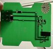
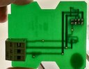
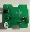
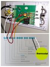
So the clever thermostat fitted,
View attachment 304576was designed to adjust the mark/space ratio as approaching the target temperature, this would have worked very well with my oil boiler, but was not suitable for the gas boiler it was fitted to as it defeated the built in modulating software.
But the problem was it worked, may be not in an efficient manor, but since it worked, it was hard to convince anyone it was wrong, I did fit electronic TRV's which took some setting up of the lock shield valves so they did not over shoot, but once set up it worked well, and gas use went down, the TRV's were claimed to work with Nest, but they didn't.


")

")
