Smart light switches everywhere - Here goes...

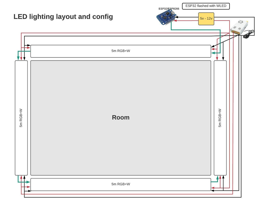
Your sketch revised.
A junction box shown in red, all the wire joints are in there.
The 2 cables between the junction box ad the switch must be as close together as possible throughout their route to reduce interference to a minimum, as indicated by the yellow ovals.
The earth wires from all 6 cables will also need to be joined together in the junction box too.
upload_2021-4-3_22-54-31.png

However by far the following is the better way of doing the job if you can get the cables into the box and switch, this is just the same as EFL's version but redrawn showing the cables
upload_2021-4-3_23-14-39.png

It gives the least interference risk and no joins. [May need a connecter for the neutral if not possible to get 4 wires in the switches neutral terminal]
 
Sponsored Links
Those sonoff switches are OK but have you looked at shelly 1's / shelly dimmers? You can then use "normal" switches of your choosing and the app doesn't report info back to china. They also support local control so are great for hooking into home assistant etc.
 
Thank you very much SUNRAY. Most appreciated. I will aim for exactly this.

SpecialKay, these Sonoffs are popular with the smart home community because they can be flashed with a custom firmware called "Tasmota", this allows you to control them without the cloud or your data ever leaving your home network.
 
without the cloud or your data ever leaving your home network

Any system that uses wireless communications on Licence Exempt frequencies can be "hacked" or it's functions compromised.

For what it is worth the lights in my cottage are controlled by relays operated by hard wired switches on a 12 volt DC system using alarm type cable between switches and relays. This method was chosen due to the problem of getting 230 V cables down lath and plaster walls

.

Five switches ( the fifth one is on the other side of the wall ) and three push buttons on a small diameter 12 core cable that can be surface mounted without being too intrusive.
 
Sponsored Links
Any system that uses wireless communications on Licence Exempt frequencies can be "hacked" or it's functions compromised.

For what it is worth the lights in my cottage are controlled by relays operated by hard wired switches on a 12 volt DC system using alarm type cable between switches and relays. This method was chosen due to the problem of getting 230 V cables down lath and plaster walls

.

Five switches ( the fifth one is on the other side of the wall ) and three push buttons on a small diameter 12 core cable that can be surface mounted without being too intrusive.
We did the same thing in a grade 1 listed building using 24Vac. However the main objective was to retain the existing switches [which was very successful] and not disturb the plaster retaining the existing cables, some of which were 19th century we believe.
 
I had planned to use "antique" switches but cost and the overall size of the necessary switch plate led me to using the "doll's house" switches
 
You say its a new build, so just fit a Megadeep switch box and put all the connections in there, no need for any Junction boxes
 
Last edited:
They certainly can be flashed with tasmota if you wish. The shellys work out the box locally - you can also flash tasmota to them. Probably have to solder them unless there is a DIY OTA flash available now?
I found they ghost switched too much and I dont like the look of them on the wall - I think they look odd...I also don't like the blue lights.
The shellys are CE certified too.

Thank you very much SUNRAY. Most appreciated. I will aim for exactly this.

SpecialKay, these Sonoffs are popular with the smart home community because they can be flashed with a custom firmware called "Tasmota", this allows you to control them without the cloud or your data ever leaving your home network.
 
Its mostly zigbee, wifi and zwave that's used now. They are generally secure and devices have to be added to the network.

Any system that uses wireless communications on Licence Exempt frequencies can be "hacked" or it's functions compromised.
 
Thats intetesting about the Sonoff stuff- i've got 3 of the 4 way relay cards doing various jobs.
Given its a clean install rather than a retrofit to existing, there would be a good case for going the plc route- low voltage signal cabling at the switchplate, one or more hidden but accessible hubs containing all the power and control gear. Do integrate some on/off functionality that t doesn't rely on functioning wifi
 
The final wiring diagram then:

Lighting-diagram-1.jpg


And in case any one is interested, my standard config for 20m of LED strips...

Lighting-diagram-2.jpg


Could easily be extended to 30m total (7.5m each) because I'm powering the strips at both ends. Currently, I'm looking at 12v 30 LED/metre strips at 0.3W per LED. So that's 9W for 1m or (9x5) 45W for 5m of LED. For 20m, max power consumption would be (45x4) 180W. At 12v that's (180/12) 15A DC. An AC-DC 200W/20A PSU should cover this (though I'll go a little higher). FYI, 20A DC translated to AC is less <1A. So my wall switch (rated at 2A per output) is more than enough. Technically, I don't have to power the LED transformer via the wall switch, because the LED controller (ESP32 flashed with WLED) can be used to switch off the lights, but this adds the ability to cut power to the PSU altogether which would be safer IMO.
 
Last edited:
The final wiring diagram then:

Lighting-diagram-1.jpg


And in case any one is interested, my standard config for 20m of LED strips...

Lighting-diagram-2.jpg


Could easily be extended to 30m total (7.5m each) because I'm powering the strips at both ends. Currently, I'm looking at 12v 30 LED/metre strips at 0.3W per LED. So that's 9W for 1m or (9x5) 45W for 5m of LED. For 20m, max power consumption would be (45x4) 180W. At 12v that's (180/12) 15A DC. An AC-DC 200W/20A PSU should cover this (though I'll go a little higher). FYI, 20A DC translated to AC is less <1A. So my wall switch (rated at 2A per output) is more than enough. Technically, I don't have to power the LED transformer via the wall switch, because the LED controller (ESP32 flashed with WLED) can be used to switch off the lights, but this adds the ability to cut power to the PSU altogether which would be safer IMO.
If it's possible I'd go for 24V tape to reduce the current.
Please ensure you have the correct version of ESP, some are not tolerant of higher voltage comms lines.
 
If not considered already wire in a relay to wled that turns on off the power supply to the leds. They probably wont use anywhere near 20A. You can current limit them in wled.
Its also very important you fuse them correctly at the DC side.
Have you looked at using a dig-uno?
 
Yep, just came across that today. Found a guy on Ebay who makes them. You're right, need to introduce some safeguards between DC outlet and the strips.
 

DIYnot Local

Staff member

If you need to find a tradesperson to get your job done, please try our local search below, or if you are doing it yourself you can find suppliers local to you.

Select the supplier or trade you require, enter your location to begin your search.


Are you a trade or supplier? You can create your listing free at DIYnot Local

 
Sponsored Links
Back
Top