- Joined
- 8 Feb 2024
- Messages
- 3
- Reaction score
- 0
- Country

Hi all, looking for some advice on what my builder has done here.
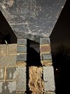
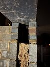
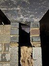
The project is a single story flat roof extension 6m x4m, with 4m bi-fold doors. The builder has placed the steel beam across the bi-fold door opening and has chosen to use 3 engineering bricks on both leafs of the wall instead of a pad stone. The SE comments are as follows:
P1 - 215mm deep x 440mm long (C-15) concrete pad
stone or 3 course of engineering bricks to full wall width.
I've attached some photos of the steel beam sitting on top of the bricks. My questions are -
1. Beneath the 3 engineering bricks there is a very small concrete block, presumably the builder put this there to help him get to height - is it ok to do this?
2. The engineering bricks are not tied into each other across the span of the cavity, is that ok, or should that have been done - just seems a bit weird that they arn't tied into each other, but i really don't know.
3. The right hand side on the outer leaf wall looks like it is leaning to the left, does it look safe and ok to leave it like this? It also looks like the mortar at the bottom is a bit patchy and not full - is that a problem, could have that caused it to lean slightly when the steel beam was lowered onto it?
I wasn't present when they lowered the beam, i didn't see how it was done. I'm also concerned that they didn't leave the bricks very long to set and laid the bricks the same day they placed the steel beam, is that a problem, how long should they usually be left for the mortar to set before placing the beam?
I could be just worrying about nothing, but would appreciate any opinions or advice on whats been done so far, should i have any concerns? I've attached the SE notes too.
Thanks very much in advance
T