Thank you so much Tony!! Very helpful!....

You are using an out of date browser. It may not display this or other websites correctly.
You should upgrade or use an alternative browser.
You should upgrade or use an alternative browser.
Steel beam sticking out of pitched roof
- Thread starter Ben Bord
- Start date
....
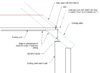
I found in catalogue UB254 that fits quite well for the level difference. When I sketched it out there is still bit sticking out. Can we cut the part of the flange that sticks out? And actually is it safe to make it the way I sketched it?
Attachments
L
Leofric
So are building control involved with this conversion and ,if so , are they happy with what appear to be raised tie trusses where the new loft floor joists will be at the level of the raised ties 
@op; (this is at your risk, and you really need to speak with your SE first)
1. make the length of the 'offcut' of UB fill the space between two rafters, and stabilize it with 100x100 angle brackets screwed to the sides of the
rafters and tight against the web - you'd need 4 brackets, 2 each side. --- blue on sketch.
2. no prob. cutting the outer half of the flange off.
3. the suitability for shear strength of the chamfered beam will depend on the load the beam is carrying, and how much vertical length of web is left at 1/3 the distance in from the inner lip of the 'spreader' beam ---- red line on sketch. This length will probably be approx. 30-40mm - your SE would be able to check as he will know the figures.
4. inspector might expect a padstone - not necessarily required structurally as it depends on the load from the beam and the strength of the brickwork,
but again the SE would know this.
5. Leofrics' point above is a valid one, which is that the load from the floor joists seems to be taken on the rafters - are they suitable for the increased load, and has anyone considered the type of fixings needed?
Bear in mind that the overriding issue in this is not the strengths of the individual parts - these can be quantified and proved - but overall stability of the detail and you have to be sure you/the builder know what you're doing. You are trying to make the best of a bad job, but you are where you are - as they say.
@op; (this is at your risk, and you really need to speak with your SE first)
1. make the length of the 'offcut' of UB fill the space between two rafters, and stabilize it with 100x100 angle brackets screwed to the sides of the
rafters and tight against the web - you'd need 4 brackets, 2 each side. --- blue on sketch.
2. no prob. cutting the outer half of the flange off.
3. the suitability for shear strength of the chamfered beam will depend on the load the beam is carrying, and how much vertical length of web is left at 1/3 the distance in from the inner lip of the 'spreader' beam ---- red line on sketch. This length will probably be approx. 30-40mm - your SE would be able to check as he will know the figures.
4. inspector might expect a padstone - not necessarily required structurally as it depends on the load from the beam and the strength of the brickwork,
but again the SE would know this.
5. Leofrics' point above is a valid one, which is that the load from the floor joists seems to be taken on the rafters - are they suitable for the increased load, and has anyone considered the type of fixings needed?
Bear in mind that the overriding issue in this is not the strengths of the individual parts - these can be quantified and proved - but overall stability of the detail and you have to be sure you/the builder know what you're doing. You are trying to make the best of a bad job, but you are where you are - as they say.
View attachment 164124
Thanks a lot Tony for all this. I have passed on the information you gave me onto the structural engineer and told him to be detailed so we can build this thing. This is what he came back with. Would you mind taking a quick look at this if it is going to work? I don't trust this guy anymore and I would like to know it's not dangerous before I will pass the drawing onto the builders.
Thanks again.
Attachments
Fancy word for isometricI declare 'axonometric' as word of the day. I don't know what it means but I'm going to use it on my next regs submission.
...and what's isometric a fancy word for?Fancy word for isometric
") ...........
..............and what's isometric a fancy word for?
Lucosade?
L
Leofric
Roughly speaking isometric projection is a 3 dimensional drawing without perspective with sides of a box for example drawn at 30 degrees to the horizontal baseline.
Axonometric is similar using 45 degree angles but can be 30/60 degrees.
Axonometric is similar using 45 degree angles but can be 30/60 degrees.
Roughly speaking isometric projection is a 3 dimensional drawing without perspective with sides of a box for example drawn at 30 degrees to the horizontal baseline.
Axonometric is similar using 45 degree angles but can be 30/60 degrees.
And there is oblique as well
")
L
Leofric
 why the
  take that.
- Joined
- 26 Aug 2016
- Messages
- 6,830
- Reaction score
- 1,009
- Country

I just thought I'd mention that Tony is the absolute genius and is definitely owed thousands of pints collectively by the forum.
Also, OP if it makes you feel better about competence, despite this being an extremely common existing roof structure that's face slappingly obvious if you are in any upstairs room, our builders made exactly the same mistake and didn't notice until they had the roof off.
Also, OP if it makes you feel better about competence, despite this being an extremely common existing roof structure that's face slappingly obvious if you are in any upstairs room, our builders made exactly the same mistake and didn't notice until they had the roof off.
DIYnot Local
Staff member
If you need to find a tradesperson to get your job done, please try our local search below, or if you are doing it yourself you can find suppliers local to you.
Select the supplier or trade you require, enter your location to begin your search.
Please select a service and enter a location to continue...
Are you a trade or supplier? You can create your listing free at DIYnot Local
Similar threads
- Replies
- 3
- Views
- 3K
- Replies
- 6
- Views
- 14K