Suppliers 12 volt LED advert and advice.

Joined
27 Jan 2008
Messages
23,629
Reaction score
2,661
Location
Llanfair Caereinion, Nr Welshpool
Country
United Kingdom
This is the advert and this
ae235
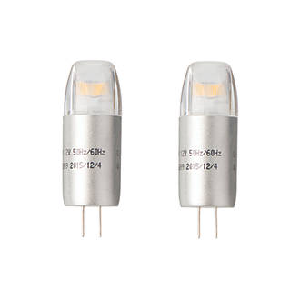
is the picture, clearly marked 50Hz/60Hz in the question and answer section the question is
Colmartin said:
does the transformer need to be upgraded for this product?
The answer
SF Product Support said:
Hello Colmartin,

When installing these products you will need to use an LED voltage Driver. This can be found under the following links:

http://www.screwfix.com/p/halolite-led-constant-current-driver-1-9w/66599

http://www.screwfix.com/p/halolite-led-constant-voltage-driver-1-16w/85503

Thank you for using Q&A
I could hardly believe what I was reading, the 66599 was completely unsuitable the units are voltage dependent, and the second is DC and the product is clearly AC unless they have used the wrong picture.

Sept 2016 would one not have expected by this time they would have seen the error?
 
Sponsored Links
Eric - I think that every time someone clicks your link they might be giving a "yes it was helpful" vote to Screwfix's answer.
 
Not worth changing, I do think it is wrong not to get replies proof read, I tried the report icon, however it does nothing it seems. Those are not the only LED bulbs clearly marked on the picture as 50/60 Hz but Screwfix have not got a toroidal transformer in their range, so likely they don't want to admit they are selling lamps, but not a suitable transformer to power them.
 
Just another example of suppliers not knowing what they are talking about.
 
Sponsored Links
I have to admit I have also made mistakes with 12 volt LED lighting, for a time I thought all 12 volt LED lighting was DC, I had fitted 4 very cheap (PoundWorld) lamps 0.58W each into my bathroom pods, it looked better with a working lamp then with a blown bulb although really not needed.

The lamps lasted about 6 weeks before failing, the GU10 versions worked OK, it was just the G5.3 12 volt versions which seemed to have a problem.

However walking through Lidi I noted their 3W versions clearly marked 50 Hz so I thought I would give it another go. Then I noted many of the 12 volt MR16 replacement lamps marked 50 Hz. Until seeing the lamps in Lidi I thought that was why my lamps failed, because powered from AC not DC.

I do wonder if the 50/60 Hz marking is a get out for when fitted to electronic transformers with a minimum output, the supplier can say it is clearly marked 50/60 Hz you have supplied it with MHz you have to expect it to fail or even transmit RF as you have used wrong supply, but why not DC/60 Hz as sure they would work on DC, one has to assume there is a reason for not marking DC/60 Hz maybe the rectifier will be overloaded?

I have seen repeatedly on these pages where people have stated you need to replace your electronic transformer with a driver, I suspect if I look back far enough I am one of those telling others you need a DC supply, even if I did not call it a driver. My first contact with lighting drivers was in an airport, seems the landing lights used drivers to ensure each one is same brightness, these were current to voltage transformers, the transformer supply was wired in series so each one was exactly the same output. So it seems drivers can be AC or DC although not seen a domestic AC version.

I some times wonder why we give items names at all, just call them all thinges, be it transformer, ballast, or drivers we don't seem to be able to define what it is.
 
I do wonder if the 50/60 Hz marking is a get out for when fitted to electronic transformers with a minimum output, the supplier can say it is clearly marked 50/60 Hz you have supplied it with MHz you have to expect it to fail or even transmit RF as you have used wrong supply ...
Maybe, but I'd been more inclined to suspect that, in many/most cases, it's more likely to be the result of ignorance than any 'cunning plot'. Only if they used a capacitor to control current would frequency be a major issue, and if that were the case they would not work at all with DC.
... but why not DC/60 Hz as sure they would work on DC, one has to assume there is a reason for not marking DC/60 Hz maybe the rectifier will be overloaded?
If they will work on both AC and DC (i.e. contain a rectifier and do not use a series capacitor), the same current will flow through the rectifier whether the supply is AC or DC.

Kind Regards, John
 
If they will work on both AC and DC (i.e. contain a rectifier and do not use a series capacitor), the same current will flow through the rectifier whether the supply is AC or DC.
Kind Regards, John
I would expect to find double the power goes through a diode with DC as with AC, as with AC it will alternate between two diodes, but with DC it will all go through one.

I would expect with a range of lamps the same rectifier is used, so maybe with a 3W lamp all is OK DC or AC but with 5W version it could overload the diode. The point is unless we can get that Clive guy to strip one down, how would we know?
 
I do wonder if the 50/60 Hz marking is a get out for when fitted to electronic transformers with a minimum output, the supplier can say it is clearly marked 50/60 Hz you have supplied it with MHz you have to expect it to fail or even transmit RF as you have used wrong supply, but why not DC/60 Hz as sure they would work on DC, one has to assume there is a reason for not marking DC/60 Hz maybe the rectifier will be overloaded?

I have found that if you run them off a SMPS at 10s of kHz they take about twice the power (watts) with no increase in brightness. I imagine the extra power s dissipated in the diodes as they would not be fast recovery types.
 
I would expect to find double the power goes through a diode with DC as with AC, as with AC it will alternate between two diodes, but with DC it will all go through one.
Whilst that is true, if it's a monolithic bridge rectifier, then is it not the total power being dissipated in the device (rather than the average current through any particular diode) that really matters? If so, that would be essentially the same with either DC or AC, wouldn't it?

Kind Regards, John
 
I imagine the extra power s dissipated in the diodes as they would not be fast recovery types.

The parasitic capacitors in parallel with each diode in the bridge have a much lower impedance at 10s of kHz than they do a 60Hz. Hence with a high frequency AC supply the bridge presents a low impedeance path between its AC terminals. ( similar for a high frequncy chopped DC supply )

Out of interest, How did you measure the power to determine it was about twice when run from an SMPS ?
 
Out of interest, How did you measure the power to determine it was about twice when run from an SMPS ?

I used a plug in power meter in the 240v side of the SMPS/transformer. I measured using MR5.3 LEDs and halogen on both a transformer and SMPS. With halogen the correct power figure was shown using both supplies. With LED the power approx doubled using. SMPS.
 
I used a plug in power meter in the 240v side of the SMPS/transformer. I measured using MR5.3 LEDs and halogen on both a transformer and SMPS. With halogen the correct power figure was shown using both supplies. With LED the power approx doubled using. SMPS.
Do I take it that this plug-in meter was measuring true power? As bernard has implied, the capacitors within the bridge rectifier (and any across the input) would be expected to considerably increase the VA at high frequencies.

Kind Regards, John
 
Do I take it that this plug-in meter was measuring true power? As bernard has implied, the capacitors within the bridge rectifier (and any across the input) would be expected to considerably increase the VA at high frequencies.

Kind Regards, John

Of course. In fact it has readouts of W, VA, V, Freq, and power factor selectable.
 
Of course. In fact it has readouts of W, VA, V, Freq, and power factor selectable.
Fair enough. Assuming that it was not a very sophisticated one, I wonder how well (accurately) it works when looking at (a small) current which has a waveform which is chopped in the way that the input to an SMPSU will usually have?

Kind Regards, John
 
Fair enough. Assuming that it was not a very sophisticated one, I wonder how well (accurately) it works when looking at (a small) current which has a waveform which is chopped in the way that the input to an SMPSU will usually have?

Kind Regards, John

Well as I said with a halogen lamp on the SMPS the reading was as expected.
 

DIYnot Local

Staff member

If you need to find a tradesperson to get your job done, please try our local search below, or if you are doing it yourself you can find suppliers local to you.

Select the supplier or trade you require, enter your location to begin your search.


Are you a trade or supplier? You can create your listing free at DIYnot Local

 
Sponsored Links
Back
Top